Better Optics
I'm considering a faster responding IR sensor, as the CNY70 does not have a response time noted in the data sheet, (a typical sign in data sheets of a something less braggable) and my o'scope measurements were in the ms range.
A photo diode based one, with built-in current amplifier, Schmitt trigger etc, maybe the QSE259, OPL551, or OPL562 plus an external IR-source, like OP140D or SEP8506-002 could work.
The QSE259 has an IR filter, is characterized at 10KHz, the OPL562 at 200KHz. Case is clear on the OP562, not sure about its spectral response.
OPL551 is a 20% faster but is 3 times less sensitive. 200KHz data rate is 5us cycle time with ns range rise/fall, and would reduce timing ambiguity.
Pure photo diode output reflective couplers may be furnished with very nice response times, but then some added circuitry is needed, and the effect may be marginal anyway for this slow sample rate, so maybe not a worthwhile dive.
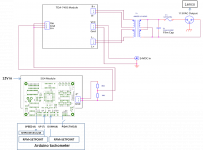
I just finished adding the tach to my SG-4 and MA-3D speed controller this weekend. I mounted the Ardunio to the side of the Galaxy chassis with an adapter plate and machined the faceplate at my work.
I used 2 Adafruit LED displays that are press fit into the faceplate along with smoked Lexan lens.
I ordered the hall sensor PCB from Oshpark and attached it to the plinth with carpet tape, soldering the SMD components was a challenge for these old eyes!
The unit to the right of the speed control is it's power supply.
Thanks to all of you that contributed to this project!
Hi Alex60Hz setup with that correction is working flawlessly.
**I did set it with 60Hz:
ADJFREQ = PIDOUT * 180; //* amount of frequency adjustment needed in 0.01 Hz
SG4 with PID - YouTube
First I want to thank You, Robnik 33 and Pyramid for all of the fantastic contributions to this site. I have learned a lot and successfully built an SG4 to work with my Lenco. I am now trying to add the speed control to the SG4 and am using the OSH sensor Pyramid referenced earlier and a 16x2 LCD display with serial backpack into Arduino uno. I am a complete beginner in coding...
I keep getting the error code 'LCD' was not declared in this scope and despite many hours trying to fix I am in limbo.
It happens in the loop at this statement-- LCD.sendString("--.---",7,1);
Any chance you could look my code over and see where I went wrong?
I truly appreciate any help you can provide.
Many Thanks
Shemply613
Attachments
Where did come up with the methods LCD.sendstring and LCD.sendfloat? They do not appear to be part of the library you are using (LiquidCrystal_I2C). You cannot mix functions or methods from one library with another (unless they both support the same syntax). If you open LiquidCrystal_I2C.h, it should show you all the methods available maybe some code examples. You may have to use lcd.setcursor() to position the cursor then lcd.print() to send the characters.
Hi All
I am a complete noob to all of this but have been able to muddle my through building and using the SG4 with my 50hz Lenco—A big Shout Out to Pyramid for all of his Fine Work.
I have now made an exact copy of Robnik 33'S sketch v7 ( Thank You!!) with the Arduino uno and the same adafruit display but still have problems using the system with my 50 hz Lenco.
Thanks
Shemply613
I am a complete noob to all of this but have been able to muddle my through building and using the SG4 with my 50hz Lenco—A big Shout Out to Pyramid for all of his Fine Work.
I have now made an exact copy of Robnik 33'S sketch v7 ( Thank You!!) with the Arduino uno and the same adafruit display but still have problems using the system with my 50 hz Lenco.
- As Robnik suggested I commented out the 45 rpm set speed
- The Tach works beautifully
- When connected exactly as shown in his drawing the sg4 switches back and forth endlessly from 55 to 70 all by itself very rapidly
- The RPM changes with each move in voltage--reaching 45+ rpm at 70v then slowing down when it shifts back to 55 v.
- The voltage constantly increases as if the up button is depressed.
- Pressing the down button while this going on has no effect.
- The only way to stop it is to pull the up and down wires from the Arduino
- All of the switches connected to the SG4 work as intended as long as they are not connected to the Arduino
- I checked every solder joint and switch and can’t find any shorts
- I inserted 220 OHM resistors between the switches and the Arduino which had no effect.
Thanks
Shemply613
Attachments
Your description is confusing. If the output voltage is switching rapidly, how does the RPM of the platter have time to change between 45+ and some other speed?
Next you state the voltage constantly increases. FYI, the up/down buttons do not change the voltage, they change the frequency.
If I had to guess, I would say your connections to the Arduino board are not correct; instead of the outputs going to the up/down buttons on the SG4, one of them may be going to the speed select switch instead, causing it to change between 33 and 45 RPM which will also cause the voltage to go to max, then drop down to the reduced voltage level.
It appears the SG4 is working properly per your post, so it has to be the connections between the Arduino and the SG4.
A couple years ago I created a turntable time indicator, how long does it take for one revolution, but not a true tachometer. I did it with hardware and was very accurate, but it showed time not rpm, so 33.333 was correct but 33.334 meant slow not fast. It was good for setting the speed of a speed adjustable table, but still not a tach.
Fast forward a couple years and I had to use an Arduino as a controller of a preamp. Steep learning curve but learned how to use the IDE and the boards. After the preamp I decided to revisit the turntable project. I was frustrated by the apparent inaccuracies for timing in the Arduino. I was down to manipulating registers in the ATMega328 chip. Tried the Timer2 Counter by Gabriel Staples and still not timing stable enough. Then I started reading this thread and when Bill/Pyramid stepped in and tried the Arduino, I read his code in Post 139 and while we are doing different things with our code, I saw the line: TIMSK0=0; //* disable timer0 interrupts. A light bulb went off in my head, of course, I am not using the other timers so shut them down so they don’t happen to take any clock cycles. Now the timing is consistent, and I don’t use any pre-scaling on the clock, just have to “Calibrate” for each Arduino clock differences. So, Thanks Bill for that info!!!! Still don’t know all that the operating system is doing behind the scenes but at least things are timing stabile.
My board uses the Nano and 5 seven segment LEDs multiplexed for the readout. And I loved the Nixie tube implementation by one of the members.
What really intrigued me was Bill’s question in post 107 about using a AT89C51 processor and programming with assembly code, and a very stable clock oscillator. The ATMega328 Data manual is 660 pages verses the AT89C51RC 35 pages, much neater. I have done assembler, many years ago, for the Intel 8086 and Motorola 68000, and enjoyed working with it and the speed and control over higher level languages like C. So, my questions are, and I haven’t really had time to look into it yet so sorry for the “dumb” questions, is there a programming environment (IDE) for the AT89C51 and assembler that you use and how did you program the chip as an embedded micro, an ISP header?
Thanks for everyone's contributions here.
I use Crimson Editor for the source code: Crimson Editor
This assembler should work on 32/64 bit windows: ASEM-51
Use Atmel's (Microchip's) FLIP software to program the chip in circuit: FLIP
If ASEM-51 doesn't work, PM me and I can e-mail the necessary .exe (it is freeware).
Crimson allows you to invoke the assembler, so it is close to an IDE.
The AT89C51RB2 is going obsolete, replaced by the AT89LP51RB2 which has a lot of additional capabilities. The only thing different that must be done from the 'C' version, the ports must be configured as the 'LP' variant defaults to input only for all pins. It takes 8 lines of code to make them quasi-bidirectional like the 'C' version.
The AT89LP51RB2 has a 16 bit timer (timer 2 8052 compatible) that can be configured for 16 bit auto reload which is done in hardware, so there is no latency and no timing errors. It also has a 4 level interrupt structure vs the ATMega328 single level.
Thanks for the info. I will look into those programs.
I really would prefer an embedded MicroP over an Arduino. While the Arduino is good for non-timing related things it is very marginal as a Turntable tach.
The oscillator on the Arduino is neither accurate nor stable.
Another steep learning curve, but learning new things keeps the mind active.")
I really would prefer an embedded MicroP over an Arduino. While the Arduino is good for non-timing related things it is very marginal as a Turntable tach.
The oscillator on the Arduino is neither accurate nor stable.
Another steep learning curve, but learning new things keeps the mind active.
Thanks for the info. I will look into those programs.
I really would prefer an embedded MicroP over an Arduino. While the Arduino is good for non-timing related things it is very marginal as a Turntable tach.
The oscillator on the Arduino is neither accurate nor stable.
Another steep learning curve, but learning new things keeps the mind active.
Oscillator stability of most Arduino boards is derived from a cheap (16MHz CSTCE16M0V53-R0, $0.15 in volume ) ceramic resonator with a +/-1% total accuracy including aging, temp drift and initial freq offset. Great for blinking LED's.
This can be replaced with something better, like a "TYKTBLSANF-16.000000" temp controlled crystal oscillator, for a few bucks, with a +/- 1ppm accuracy.
Dev boards for micro controllers usually does not include three dollar oscillators, the +/-100ppm is very common.
Looked at Mouser offerings and see 138 Crystals at 16 Mhz and 10 ppm, best I could find, and $0.65 each.
Regardless of Oscillator quality, this evening I finished testing the timers on the Nano which also uses the ATMega328P processor, same as the Uno. Timer0 is an 8 bit timer and is used for system tasks and is the least consistent in timing, probably too much overhead going on behind the scenes. Timer1 is a 16 bit timer, with the other timers shut down it has some mild timing inconsistency, not good enough for turntable timing. Timer2 which is an 8 bit timer is the most consistent in timing and is usable, barely, with the other timers shut down. Different pre-scaling was tried on each timer. None would be as good as a processor running dedicated assembly code.
Another minor timing issue I found is the hall effect sensor location and the size and strength of the magnet. I have been using the Littlefuse 55100-3H-02-A, which works well with the small spot magnets. It has mounting ears which is nice but a touch on the expensive side at $10 each. I will have to try the Diode Inc. AH3376-SA-7 at $0.63 each, but that will require making a small mounting PCB.
I will have to try the Diode Inc. AH3376-SA-7 at $0.63 each, but that will require making a small mounting PCB.
Already addressed here: https://www.diyaudio.com/community/...player-lcd-display.301609/page-4#post-5113513
I believe the PN listed for the 1K resistor was for an 0603 package, but it needs to be an 0805.
Putting another oscillator on that PCB would require some soldering skill, a microscope, and patience. There is no drop in sub for that measly resonator. I made a board with the TCXO next to it and ran a short wire to the vacated foot print of the resonator.I see that Crystal Oscillator on Digikey. Unfortunately the Nano uses a crystal only so not a straight forward plug and play like some of the other uP, though I still thought about that swap. Still looking for a good crystal to replace the one on the Nano.
For ultimate freq stability one could use a GPSDO (~$95 on eBay) and add a 1.6x multiplier chip like NB3H60113G. This chip could also generate 18.432MHz for the SG-4, but not on the same chip, a second one would be needed.
Yeah, the Nano has that very small resonator whos foot print is difficult to find a replacement. Wiring in a crystal could be done but I am looking at a couple other MicroP boards that have better crystals foot prints as a possibility. Today I tried an external oscillator, 10 Mhz 2.5ppm, divided by 100 by another chip down to 100khz clocking a Nano's pin and using Pin Change Interrupt to count and while that was more accurate it consumed so much processor time that there wasn't enough clock cycles left to run the multiplexing of the five seven-segment LEDs displays fast enough to stop strobing. So, scrap that idea. I still think an embedded processor running assembly code with no other overhead is the way to go for timing tasks. A few people I know are running car fuel injection system with a DIY embedded processor board so a tach should be easier.
After reading the data sheet a little more for the ATMega328 I found you can supply the timer directly with an external clock, without the overhead of an interrupt. Timer1 using pin PD5 also called T1 so that 10 Mhz Oscillator 2.5 PPM divided by 100 by and external chip.
using:
TCCR1B = 0b00000111; //external clock source
TIMSK1 = 0b00000001; //enable Timer overflow interrupt.
TIMSK0 = 0b00000000; //disable Timer0 interrupts.
TIMSK2 = 0b00000000; //disable Timer2 interrupts.
I was able to achieve .00006 accuracy.
using:
TCCR1B = 0b00000111; //external clock source
TIMSK1 = 0b00000001; //enable Timer overflow interrupt.
TIMSK0 = 0b00000000; //disable Timer0 interrupts.
TIMSK2 = 0b00000000; //disable Timer2 interrupts.
I was able to achieve .00006 accuracy.
Hi would someone be able to help me
I am using the SG4 + the MA-3D which I got to work just fine however I am trying to add the tachometer using Arduino + seven segment display +backpack using "tach_7seg_r7-txt"code provided in Shemply613 Post above. It seemed to load fine. But right now I'm getting just straight dashes represented on the display? I'm thinking it's because I don't have my Hall effect sensor wired correctly? what pins on that Arduino board should I be going to?
I am using the SG4 + the MA-3D which I got to work just fine however I am trying to add the tachometer using Arduino + seven segment display +backpack using "tach_7seg_r7-txt"code provided in Shemply613 Post above. It seemed to load fine. But right now I'm getting just straight dashes represented on the display? I'm thinking it's because I don't have my Hall effect sensor wired correctly? what pins on that Arduino board should I be going to?
Last edited:
There should be 3 connections between the Arduino and the sensor: 5V, Gnd and Output. 5V and Gnd should be self explanatory, and the sensor output goes to PB3. If you are using the PCB available at OshPark and a cable with a 3.5mm stereo connector (Tip/Ring/Sleeve), Tip is the sensor output, Ring is 5V and Sleeve is Gnd.
- Home
- Source & Line
- Analogue Source
- Digital Tachometer for record player (LCD display)