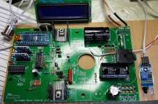
If anyone is interested I have just completed a PCB with 2 x DDS sinewave generators, class A motor drivers, digital tacho, all powered by an Arduino. Everything is controlled by software so phase angle and motor coil drive amplitude can be adjusted in software for minimum vibration. The tacho sensor is in a feedback loop that locks in the frequency of the drive to maintain exact 33.3 or 45 rpm. There is an LCD output for the information. I built it as a replacement for my Linn Valhalla and its a drop on replacement. Currently I have built a prototype PCB. If anyone is interested will post pictures.
I'm interested if you like to share your project it would be a great addition to this forum and may also involve others with ideas to help you develop and fine tune it to perfectionIf anyone is interested I have just completed a PCB with 2 x DDS sinewave generators, class A motor drivers, digital tacho, all powered by an Arduino. Everything is controlled by software so phase angle and motor coil drive amplitude can be adjusted in software for minimum vibration. The tacho sensor is in a feedback loop that locks in the frequency of the drive to maintain exact 33.3 or 45 rpm. There is an LCD output for the information. I built it as a replacement for my Linn Valhalla and its a drop on replacement. Currently I have built a prototype PCB. If anyone is interested will post pictures.
")
Hi Greggan,
I had started this before I found a number of threads on Diyaudio primarily as a replacement for the Linn Valhalla board. These are the "features" of my project:
• Electronic switching between 33.3 rpm and 45 rpm (no more pulleys)
• Highly accurate sine wave frequency synthesis generated for 50Hz or 67.5Hz controlled to 0.001 Hz
• Class A motor drive circuitry.
• Optional optical platter feedback sensor to lock platter rotation at exactly the right speed. This runs a PID controller loop reach maximum speed quickly then keeps rotation speed locked rock solid.
• Control over motor parameters such as frequencies, phase angle, voltage amplitude via a USB serial interface. Adjusting these values enables smoothest motor operation with minimum motor noise and vibration. Values may be written to EEPROM once optimum setup achieved.
• Optional LCD display to indicate exact platter rotation speed
• Fits on original Linn Valhalla mounting
• Can connect to original Linn power switches. Speed change controlled by holding power switch for three seconds
• Less heat generated than original Valhalla due to redesigned PSU section (no more burned out resistors). The picture attached shows an RC PSU but I have since changed this to a switching design due to LCD current requirements.
• May be used for other turntables that use a two phase synchronous motor such as Airpax, Premotec, Philips e.g. Rega, Linn, Manticore, ProJect etc.
• Can be housed in a separate box with LCD display.
• Uses standard commonly available low cost parts such as Arduino, AD1933 DDS generators, common transistors.
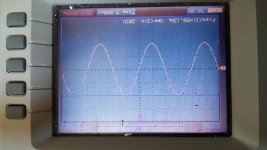
The “breadboard” prototype I built works fine and I am just in process of building second Class A amp on PCB so only one output is shown on the scope and it’s a nice clean sine wave (plus I need to drop the amplitude down - controllable in software).
So my current tasks are finalise this PCB, change design of PCB to accommodate swichmode PSU and to correct some of the minor errors.
I had started this before I found a number of threads on Diyaudio primarily as a replacement for the Linn Valhalla board. These are the "features" of my project:
• Electronic switching between 33.3 rpm and 45 rpm (no more pulleys)
• Highly accurate sine wave frequency synthesis generated for 50Hz or 67.5Hz controlled to 0.001 Hz
• Class A motor drive circuitry.
• Optional optical platter feedback sensor to lock platter rotation at exactly the right speed. This runs a PID controller loop reach maximum speed quickly then keeps rotation speed locked rock solid.
• Control over motor parameters such as frequencies, phase angle, voltage amplitude via a USB serial interface. Adjusting these values enables smoothest motor operation with minimum motor noise and vibration. Values may be written to EEPROM once optimum setup achieved.
• Optional LCD display to indicate exact platter rotation speed
• Fits on original Linn Valhalla mounting
• Can connect to original Linn power switches. Speed change controlled by holding power switch for three seconds
• Less heat generated than original Valhalla due to redesigned PSU section (no more burned out resistors). The picture attached shows an RC PSU but I have since changed this to a switching design due to LCD current requirements.
• May be used for other turntables that use a two phase synchronous motor such as Airpax, Premotec, Philips e.g. Rega, Linn, Manticore, ProJect etc.
• Can be housed in a separate box with LCD display.
• Uses standard commonly available low cost parts such as Arduino, AD1933 DDS generators, common transistors.
The “breadboard” prototype I built works fine and I am just in process of building second Class A amp on PCB so only one output is shown on the scope and it’s a nice clean sine wave (plus I need to drop the amplitude down - controllable in software).
So my current tasks are finalise this PCB, change design of PCB to accommodate swichmode PSU and to correct some of the minor errors.
Attachments
Last edited:
Looks great but kind of dangerous
I understand the idea of being able to keep the original motor but
my plan i to use a 12-24V AC Synchronous motor to keep it safe to tamper with.
The necessary step down transformer will make it lightly more expensive but also give a isolation from mains and act as a kind of filter and that is not a bad thing
However I would still love to try your take on this do you plan to sell some PCB's and share your code and schematics?
If so any idea
scobham:
Might you have any interest in broadening the utility of this project by allowing for 60hz line voltages and non-Valhalla applications? Bill Carlin's SG-4 turntable motor project is great but doesn't allow for an optical platter feedback sensor. I'd like to build a system that assures rotational accuracy.
Regards,
Scott
Hi Greggan,
yes one needs to be careful. For my testing I use an isolation transformer - a 100mA 220V secondary as I need to be able to use my oscilloscope and I find differential probes a pain. No need to add any filtering though with an additional transformer in actual operation. I must admit I did not think of driving 12-24V AC motors. Currently the lowest output I designed the circuit for was 50V but I may be able to modify the circuit to get down to 12-24V AC levels.
I probably will make the PCB's available as a group buy with a pre-programmed Arduino that contains the code. Not really thought that far yet. Plus I have a mountain of parts (transistors, capacitors, diodes etc) so I may offer a small kit of parts for anyone interested.
Hi SRMcGee, yes the new switching PSU will accept an input voltage 85V - 240V 50Hz or 60Hz so it can be used anywhere worldwide. You can set the motor drive output frequency up to 100Hz if you are using 60Hz motors. That would get you up to 45rpm (and a bit beyond) - I think that probably satisfies your needs. I actually use this on my Manticore Mantra so 100% with you on non Linn applications. I am trying to make this universal.
Regards,
Steve
...
I probably will make the PCB's available as a group buy with a pre-programmed Arduino that contains the code.
...
I'm interested - Thanks for your efforts.
Hi Scobham.
Very interesting stuff.
I'm looking for psu+optical sensor combo for a long time now.
My first option was Phoenix Engineering Falcon + Roadrunner, but it was a bit pricey back then and now this produckt is no longer available.
Then there was MagicQuartz YouTube
This project is still not released, and there are no news from creator.
That's a pitty because his product has great potential and very cool ideas.
There was free arduino version. You can still access it from wayback machine.
Breadboard Version | MATE-LABS
I'm using Avid Ingenium. It has AC 12mNm ac synchronous motor. Not sure about it but I guess I'll need 12-24V version too, right?
Hi Gregorjank, thanks for the info. I did look at the site - the free design only appears to generate one phase supply although speed is checked with an optical sensor. The purpose of my project is to provide separate drive signals for each motor winding so fine control of phase is possible and voltages to reduce motor vibrations and noise. As you say seems to have disappeared as a project. I think 12mNm probably specifies the torque rather than the voltage - check the motor model number or label and ensure its not a DC motor.
Hi sq225917, (and Greggan) well I am happy to report that with a slight circuit modification I can generate any sinewave voltage from 4v up to 225v controllable from software. (Each phase can have its own voltage setting). So that means a whole range of extra options for the motor now available. e.g. Rega 24v synchronous 2 phase AC motors. I will build this modification into the revised PCB.
Steve
So just an update.
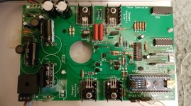
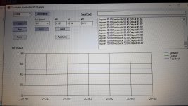
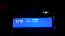
New prototype PCB’s arrived with the re-designed efficient PSU. First prototype built and tested – see picture. No LCD attached at the moment to this one as need to wire that up. Software in a more or less ready state. Its working both as open loop and with PID control. I want if possible, to add auto-tuning for the Kp, Ki, Kd parameters as they can be quite fiddly to work out manually. The PID control loop achieves full stability after about 20 seconds reading 33.333 rpm but I would like to think I can make this quicker with better tuning. I also need to test 110V operation and trying to find smaller height PSU capacitors so they don’t need to be mounted on their side when installing in say a Linn LP12 and replacing a Valhalla board.
I have also had a request if this board will supply shaded pole motors – the answer is yes but the current board configuration expects the motor to draw about 8mA per winding. So motors with larger current consumption will need larger heatsinks for the transistors and possibly larger output capacitors. Currently testing what’s practical.
Attachments

That looks promising
I have also made some progress with my tacho project.
It has now a 3D printed enclosure and the project website is updated with all the details and downloadable cad files so that anyone can download them and build their own
DIY LP Turntable tachometer |
I have also made some progress with my tacho project.
It has now a 3D printed enclosure and the project website is updated with all the details and downloadable cad files so that anyone can download them and build their own
DIY LP Turntable tachometer |
The point that attracts me in that project is the feedback (or you called it close loop). I’m happy with Arduino, but still my speed is quite variates. Speed on records beginning, its mid section and at its end is quite sloppy. Hot or cold motor is also considered as a variable (specifically with motors like mine, 120VAC 2W). If feedforward PID can be set to reasonably tight window in short time frame, then it will be the winner against Arduino and I’ll go for it, for sure.
Hi Greggan,
that enclosure looks super and solves a problem of both sensor and display wiring and packaging.
Alex, I do use an Arduino on the PCB to actually carry out the PID calculations and interface with the LCD and sensor. getting 33.334 from my Manticore Mantra with the last digit fluctuating slightly when using PID. Yes that is where the work is at the moment to get the window tighter.
The other slight issue is that I am 80% used on code space so I have to re-write some of the serial driven setup menu's to be more efficient. I need the extra space as I would also like to add some motor current sensing facility to drop the drive voltages down when running at full speed to reduce motor noise and vibration.
Steve
That looks promising
I have also made some progress with my tacho project.
It has now a 3D printed enclosure and the project website is updated with all the details and downloadable cad files so that anyone can download them and build their own
DIY LP Turntable tachometer |
That's very clever! I like it! Just be sure to experiment with damping to see if that device or the USB cable dangling from it effect the sound at all. I wonder if a right-angle connector is available for that cable to reduce strain on the jack too. I really do like that approach overall, though!
As I mentioned in my project website I'm looking in to a design with a thin and flexible USB power lead that is fixed (like direct soldered to the Arduino PCB) and will exit at the plater side of the display casing. This way it will be possible to route the wiring underneath the platter an slip it between the cover and plinth at the back of the TT to make it neat 
Well the turntable controller prototype is debugged, tested and finished.
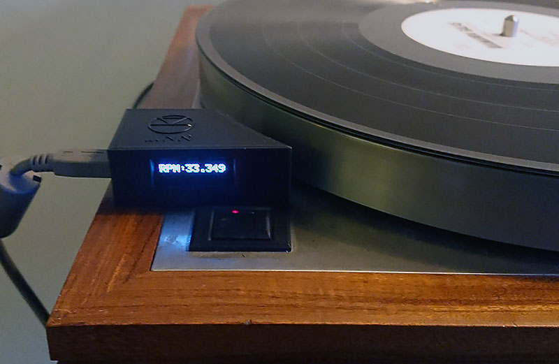
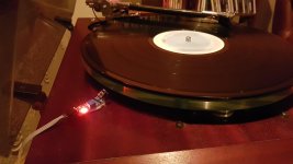
A couple of screen shots below showing the sensor (which needs a nice enclosure like Greggan has made), the LCD showing measured speed locked at 33.333 rpm and a picture of the completed PCB. I have my PCB mounted in a separate enclosure. I am using the Linn Valhalla switch to control but it can be any switch (there are separate connectors on the PCB). Electronic switching up to 45 rpm works fine.
I am planning on making this a group buy if anyone is interested. Options will be a 1) bare PCB with pre-programmed arduino nano, 2) bare PCB with pre-programmed arduino nano and a full kit of parts, 3) fully assembled board.
The board can be used without a sensor to provide stable 50 / 67.5 Hz, with sensor just to read tacho speed, or full PID closed loop mode where the motor speed is adjusted based on sensor feedback. (The PID tuning is a manual process as I have not been able to make the autotune routines produce good results. However, I have a procedure for determining the Kp, Ki, Kd PID parameters manually).
The design is a drop-in replacement for the Linn Valhalla but will work with any turntable using a synchronous aka Airpax, Premotec, Philips motor 9V – 115V.
The board will work 110v – 240v and drive 2 phase motors. By daisy chaining a second board (less PSU, LCD and arduino components) 3 or 4 phase motors can also be driven as long as they operate on 9v – 115v RMS at about 10mA max per phase.
I need to write a full set of assembly and setup instructions yet but probably need a few beta testers for the kits.
Attachments
- Home
- Source & Line
- Analogue Source
- Digital Tachometer for record player (LCD display)