I am working on a MM phono preamp. Its based on the LME49720 datasheet circuit. There are quite a few existing designs based on this circuit like CNC, muffsy etc but I wanted to make my own board.
I have used jumpers to switch between the two sets of input loading. A dpdt switch can also be used for switching this. This way two different TTs can be supported.
I have added a jfet ccs (Idss – 6-8ma) to both gain stages to run them in class A mode. Its a single shared ccs for both gain stages of a channel.
I have quite a few opamps, so will experiment with those, like ne5532, opa2134, 49725, 4562 etc.
I plan to use a dual shunt regulated supply at about a volt less than the max allowed by the opamp.
Any suggestions to make it better?
Updates:
CCS - Removed
Used a different RIAA network. It sims better and sounded better to me.
Final Schematic -
Simulation results -
PCB Layout -
PCBs and Kits are available Now.
Pricing:
Bare PCB – 7$ each.
PCB and 2ch Components kit (Tightly Measured RIAA and Gain Components) – 30$.
Shipping to anywhere:
For PCB only – 2$ for first PCBs, 1$/PCB after that.
For PCB and Kits – 3$ per kit
I have used jumpers to switch between the two sets of input loading. A dpdt switch can also be used for switching this. This way two different TTs can be supported.
I have added a jfet ccs (Idss – 6-8ma) to both gain stages to run them in class A mode. Its a single shared ccs for both gain stages of a channel.
I have quite a few opamps, so will experiment with those, like ne5532, opa2134, 49725, 4562 etc.
I plan to use a dual shunt regulated supply at about a volt less than the max allowed by the opamp.
Any suggestions to make it better?
Updates:
CCS - Removed
Used a different RIAA network. It sims better and sounded better to me.
Final Schematic -
An externally hosted image should be here but it was not working when we last tested it.
Simulation results -
An externally hosted image should be here but it was not working when we last tested it.
PCB Layout -
An externally hosted image should be here but it was not working when we last tested it.
PCBs and Kits are available Now.
Pricing:
Bare PCB – 7$ each.
PCB and 2ch Components kit (Tightly Measured RIAA and Gain Components) – 30$.
Shipping to anywhere:
For PCB only – 2$ for first PCBs, 1$/PCB after that.
For PCB and Kits – 3$ per kit
Last edited:
target 100x100mm max to get pcb fab deals
C107/207, move down like C105/205
Thick returns on C104/204
R115/215 does not need to be so high, 100 is fine
C112/212 should be bigger, 10uF min, what a is the worst case load?
copper pour ground to the connector, thermal pad, no need for narrow traces.
C107/207, move down like C105/205
Thick returns on C104/204
R115/215 does not need to be so high, 100 is fine
C112/212 should be bigger, 10uF min, what a is the worst case load?
copper pour ground to the connector, thermal pad, no need for narrow traces.
simulate the design in ltspice first, just to be certain you got it right.
Quick sim shows it to be "pretty awful" ...
Last edited:
target 100x100mm max to get pcb fab deals
C107/207, move down like C105/205
Thick returns on C104/204
R115/215 does not need to be so high, 100 is fine
C112/212 should be bigger, 10uF min, what a is the worst case load?
copper pour ground to the connector, thermal pad, no need for narrow traces.
I plan to use a 2.2uf cap at the output. Cap is 27.5mm pitch, so many 10uf may not fit. It will be driving a preamp, so I guess the worst case load will be 20k. Its probably not usual having a preamp with 10k input impedance.
R110 and R111 - shouldn't they be connected "in series"?
Good catch, thanx a lot...
Quick sim shows it to be "pretty awful" ...
Actually its not all that bad, but looks like the ccs in the second stage is messing up the hf response. I took out the ccs. The 10R didnt work with the ccs, 100R works ok, but hf issue remains.
I changed the RIAA values for a better response, looks quite good to me. I added the simulation and other images to the first post. The variation is about 0.1db in the response.
Last edited:
I changed the RIAA values for a better response, looks quite good to me.
Can you put up a simulation with CNC phono original filter values?
So that we could see if your version is actually better.
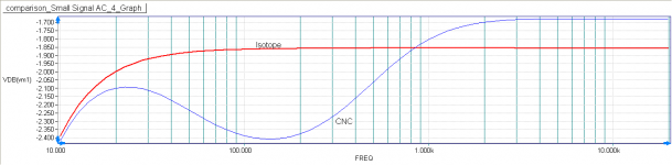
Sure, here's the cnc phono sim. I kept the gain and load same. Its quite good, the plot is within 0.25db. Mine is in 0.1db with a flatter plot.Can you put up a simulation with CNC phono original filter values?
So that we could see if your version is actually better.
An externally hosted image should be here but it was not working when we last tested it.
I was able to combine both into a single screen shot. Green is cnc and blue is isotope.
An externally hosted image should be here but it was not working when we last tested it.
Where have you taken the signal source schematics from?
I am using one (from :: View topic - RIAA and iRIAA accuraccy in the real and simmed world. ) with a bit other values for the invRIAA-filter and getting a better result with the CNC phono standard values.
Also Rser has been set to 0 .
IMO C1 should be set to something like 100...200 pF to resemble "real life"...
And how do you get the gridlines on the graph?
As you're using through hole components, checkout NAT SEMI's application note AN-1651 (available from TEXAS Instruments web site - search for SNAA046).Any suggestions to make it better?
The RIAA amps use the same topology as your current circuit, with 'off the shelf' component values for the RIAA equalisation and DC offset servo correction.
The KAB PASSIVE RIAA EQ NETWORK COMPUTER is also helpful in calculating component values for RIAA equalisation (try 11k for R1).
The PCBs are looking good. Here's an example with lots of onboard smoothing caps.
Good Luck!
Where have you taken the signal source schematics from?
I am using one (from :: View topic - RIAA and iRIAA accuraccy in the real and simmed world. ) with a bit other values for the invRIAA-filter and getting a better result with the CNC phono standard values.
Also Rser has been set to 0 .
IMO C1 should be set to something like 100...200 pF to resemble "real life"...
And how do you get the gridlines on the graph?
I think the iriaa source came from jung paper.
I tried the one you posted, it gives better results. I calculated the values from equations and the inverse riaa you posted shows a lot better graphs than the previous one.
There is an issue with this iriaa though, it doesnt show the db level correctly. Its incorrect right at the output of the iriaa. The final output is about 1v peak, but it shows about 38db output. For now I have ignored this and looking at just the relative curves.
I used these calculations to calculate the values. The original equations started with a standard resistor r1, I changed it to use cap c2 as a starting point. t1,t2,t3 are the time periods. I hope these are correct or I am back to the drawing board.
c2uf=c2/1000;
r1=((t1*t3)/t2)/c2uf;
r2=r1/(((t1-t2)*(t2-t3))/(t2 * t2));
c1=1000*t2/r2;
I also added a third cap to the riaa rc filter, just in case its needed.
Sims with new values -
An externally hosted image should be here but it was not working when we last tested it.
The grid lines are there on the right click menu->Grid (or use Ctrl-G key.
As you're using through hole components, checkout NAT SEMI's application note AN-1651 (available from TEXAS Instruments web site - search for SNAA046).
The RIAA amps use the same topology as your current circuit, with 'off the shelf' component values for the RIAA equalisation and DC offset servo correction.
The KAB PASSIVE RIAA EQ NETWORK COMPUTER is also helpful in calculating component values for RIAA equalisation (try 11k for R1).
The PCBs are looking good. Here's an example with lots of onboard smoothing caps.
Good Luck!
Thanx, 11k is a good value, though I ended up using other values.
That one is using the extra caps in the psu section, looks like a lm317/337 supply.
I had space and tracks were going there, so I added an extra set of caps anyway. Could be useful in case there is a low value high quality cap available and it needs a bigger brother.
I have updated the schematic and the pcb layout in the first post.
Thats still atleast a couple of months away.When can we expect a kit?
Any chance to try it with exotic opamps (with adapters, if needed)? I liked the sound of OPA2134 the most on the CNC but just couldn't stand LME49990. I would love to try other opamps.
Will your mini shuntreg work for this?
")
Most of the good duals should work fine. I simmed opa2134, found no difference. PCB uses dip opamps, so sockets can be used for smd opamps.
Mini shuntreg will work fine for the psu, thats what I plan to use.
If you just could keep the graph at least horizontal until 20 kHz ...
I am a bit "allergic" to muffled highs ;-)
If you develop boards for sale at one point of time, let us know ...
In sims, its down by 45mdb at 20khz. I dont think it will be audible.
I just ordered the PCBs. Thanks a lot for all the help guys. Will post once PCBs arrive
.I think the iriaa source came from jung paper.
I tried the one you posted, it gives better results. I calculated the values from equations and the inverse riaa you posted shows a lot better graphs than the previous one.
There is an issue with this iriaa though, it doesnt show the db level correctly.
Did you check the accuracy of the iRiaa circuit you have ?
Can you post the .asc file of the circuit you simmed ? ( the ckt you posted)
Thanks.
In practice you should pick your capacitors first and ensure they have the same ratio with each other as the original but not necessarily the exact value. So if you pick one , say 33nf , measure it and then pick the other cap to match up keeping the ratio 97.3/33.37 the same ( using multiple caps !). Then select the resistors to match them. Either by keeping the same RC values as the sim or from the equations. You can use more than one resistor to get what you want. Always have space for two in series for each of the RIAA resistors. Since this is a passive eq it will not affect the gain if values are different from the sim you did.
Last edited:
You need to consider that the phono cartridge itself is a big variable. The internal inductance/resistance will bring down the HF . In practice the mechanical resonance of the stylus assembly will prop up the falling HF and improve it a bit. You can increase the load resistance and decrease the load capacitance and try to improve matters. However without a test disc this will be difficult to check except for "what kind of sound you prefer".
Capacitance might be the biggest problem. Consider the following situation. Amp input capacitance 100pF, RCA interconnect cable capacitance 60 pF ( very optimistic !), Tone arm cable capacitance + connector capacitances, about 40 pF, already gives you 200pF. In practice this might be exceeded ! Could probably add up to 350pF or more and possibly very hard to get it lower !
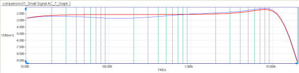
The Shure M97xE needs 250pF and 47 K ohms as the recommended load and you might be able to tweak it to get what sounds better to you ! As you try to extend the reach of the HF , the upper mid starts to sag. As usual , nothing comes for free !However lots of scope to tune it to what you like rather than what's exact !
I used R = 1.55K and L = 500mH ( Shure M97xE ) at the input. This is the resulting response. Red is Isotope, Blue is CNC.
Edit: I might add that tweaking it to get what you like to hear is perfectly OK. The whole chain from source of sound to the loudspeaker is imperfect with several if not a hundred points where it could change. So you will never get the EXACT original signal. So you can tweak it to your preference and it doesn't have to be 'exact' .....'exact' is not practically possible! Why do people prefer different cartridges ? Each person has a different preference !
Capacitance might be the biggest problem. Consider the following situation. Amp input capacitance 100pF, RCA interconnect cable capacitance 60 pF ( very optimistic !), Tone arm cable capacitance + connector capacitances, about 40 pF, already gives you 200pF. In practice this might be exceeded ! Could probably add up to 350pF or more and possibly very hard to get it lower !
The Shure M97xE needs 250pF and 47 K ohms as the recommended load and you might be able to tweak it to get what sounds better to you ! As you try to extend the reach of the HF , the upper mid starts to sag. As usual , nothing comes for free !However lots of scope to tune it to what you like rather than what's exact !
I used R = 1.55K and L = 500mH ( Shure M97xE ) at the input. This is the resulting response. Red is Isotope, Blue is CNC.
Edit: I might add that tweaking it to get what you like to hear is perfectly OK. The whole chain from source of sound to the loudspeaker is imperfect with several if not a hundred points where it could change. So you will never get the EXACT original signal. So you can tweak it to your preference and it doesn't have to be 'exact' .....'exact' is not practically possible! Why do people prefer different cartridges ? Each person has a different preference !
Attachments
Last edited:
- Status
- This old topic is closed. If you want to reopen this topic, contact a moderator using the "Report Post" button.
- Home
- Source & Line
- Analogue Source
- Isotope: Opamp based MM phono