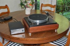
Yes, it's definitely working great. Sounds very nice - I've been listening to it for the past couple hours. Attached is a photo of the table and controller.
Now that's finished, I do have a question: What is the difference between the Papst motor and the Hurst motor used in the VPI tables? I think I understand that the Papst is a 3 phase synchronous - correct? So how is the Hurst different? I'd appreciate this information purely for my education, thanks.
Now that's finished, I do have a question: What is the difference between the Papst motor and the Hurst motor used in the VPI tables? I think I understand that the Papst is a 3 phase synchronous - correct? So how is the Hurst different? I'd appreciate this information purely for my education, thanks.
Attachments
The Papst motor is a 3 phase hysteresis type which is synchronous, but has some differences from a typical AC synch motor. It does not use a permanent magnet for the rotor, so it does not exhibit cogging. Because of this, it is smoother, but can fall out of synch at higher torque loads (an AC synch motor maintains speed until it stalls), is less efficient and has a lower power factor than a similarly sized AC synch motor. Both motors require higher voltage to maintain torque at higher speeds, the the Papst motor can start to "slip" similar to an AC induction motor at 45/78 RPM (drop below speed, but still spin), where an AC synch motor would stall.
IMHO, the Hurst motors are cheaply constructed, the bearings and rotor being the weak points, both inconsistent from one motor to the next. The rotors do not appear to be well balanced and coupled with a sloppy bearing (and only one bearing at that, on the top only), some motors exhibit unacceptable vibration as well as the expected cogging.
Nice looking table and good job of construction BTW.
The Papst motor is a 3 phase hysteresis type which is synchronous, but has some differences from a typical AC synch motor. It does not use a permanent magnet for the rotor, so it does not exhibit cogging. Because of this, it is smoother, but can fall out of synch at higher torque loads (an AC synch motor maintains speed until it stalls), is less efficient and has a lower power factor than a similarly sized AC synch motor. Both motors require higher voltage to maintain torque at higher speeds, the the Papst motor can start to "slip" similar to an AC induction motor at 45/78 RPM (drop below speed, but still spin), where an AC synch motor would stall.
IMHO, the Hurst motors are cheaply constructed, the bearings and rotor being the weak points, both inconsistent from one motor to the next. The rotors do not appear to be well balanced and coupled with a sloppy bearing (and only one bearing at that, on the top only), some motors exhibit unacceptable vibration as well as the expected cogging.
Nice looking table and good job of construction BTW.
Thank you for the information - it's most appreciated.
Hello. Great post and so much information and easy to get lost. I’m lazy. Lol
Is there anyone here who would build a complete unit for me? The controls and a motor? I have a few tables I could use for testing. So please help. As my hands do t work so well any longer with small parts
Thanks
Is there anyone here who would build a complete unit for me? The controls and a motor? I have a few tables I could use for testing. So please help. As my hands do t work so well any longer with small parts
Thanks
Just built my with Tda7492 on board. Works fine, but the outgoing toroidal maks a huming noise even without any load. After some suggestion from the internet added an Dc blocker to each chanel and immediately the 50Hz humm noise gone away. Had anybody similar issue? Any idea how to avoid that the amp is generating DC? Dc blocker how such looks:
PCB for DC Trap Blocker Filter for toroids – v.2 | ATL Audio Ltd.
PCB for DC Trap Blocker Filter for toroids – v.2 | ATL Audio Ltd.
Pyramid & Co.:
A friend has asked me to build him an SG-4 and I'm considering doing it for fun, but I have not been able to find the LM3886 (MK-154) amplifier that was available when I built my own unit a few years ago. Pyramid suggested a TDA-7492-based amplifier as an alternative, but the link on eBay no longer works. Is this TDA-7492 amp suitable for an SG-4 build:
TDA7492 2 x 50W D Class High-Power Digital Amplifier Board AMP Board+ Radiator | eBay
Thank you,
Scott
Potentially dumb question, but I've been thinking about building a speed controller for an old Pro-ject Debut Carbon that runs with a motor rated for 16VAC, hopefully to eliminate motor vibration. The Debut uses a 15V wall wart and a capacitor to generate a phase shift.
From skimming over this thread, it seems most synchronous motors in turntables are rated for 110 mains. Would it be possible to power this motor straight from the TDA7492 (bypassing the built in phase shift cap), or would I need to select output transformers? Would it be better to just make a power supply that powers the 15VAC wall wart, skipping the phase shifting all together?
Thanks
15VAC is just over 21Vpeak, so you should be able to run it directly from the TDA7492 outputs if you feed the amp from a 24VDC source (you *will* need a way to test and make sure the output waveform is not clipping, b/c you will be running close to the rails). As you mention the output transformers are simply to step up the voltage in order to drive the higher impedance of the 115 VAC motors.
As for "skipping the phase shifting", the purpose of this PSU is not only to allow us to adjust the frequency (and thus the speed of the turntable) but also to attempt to minimizing the mechanical noise coming from AC motors. This is provided via a number of adjustments:
1) getting as near a 90-degree phase difference between the legs as possible
2) matching the voltages applied to each leg of the motor
3) providing a sufficiently high "starting" voltage and then reducing it to a much lower level during playback
4) allowing all the above to be tweaked to match the variation in the physical characteristics of each turntable and motor setup
There are other ways of accomplishing some of the above (eg. trim pots on each leg of the motor for voltage matching) but it's nice to have it all in one (relatively) simple unit.
-b
Last edited:
I found this LM3886 amplifier board with heatsinks on Eb..
Description
Applicable Voltage: 12-28V ×2 (Double AC)
Power Supply: Proposal not less than 200W
Output Power: 68W ×2
Output Impedance: 4-16Ω
Sound Channel: 2 Channel stereo
Circuit Architecture: LM3886 + OP07 + NE5534
Product Features: Preceding stage voltage regulator, DC servo, Include heatsink and other protection
Protection Characteristics: Overheating protection, DC Safeguard, Short circuit protection
Product size: 149.6 × 135 × 52 mm
Weight: 550g
You will receive
1pcs New LM3886 Stereo Power Amplifier Board Kit
SKU# FA.PP.778
Shipping Weight: 24 oz
Net Weight: 23.4 oz
(0-FR Envelope;1-Padded Envelope;0-BoxA;1-Medium FR Box;4-Large Box)
It if feasable for this project?
Amps and Connectors
I noticed this amp on sale at PartsExpress and it seems like a potential candidate for the back end of the SG4:
TPA3116D2 2x50W Class D Stereo Amplifier Board with Volume Control
It has a built-in attenuator, which should eliminate the need for a separate pot on the SG4 output. It's also d**m cheap.") Has anyone played with this unit?
Has anyone played with this unit?
Also, there have been several posts on connecting the SG4 to the actual turntable, specifically for the 115V synchronous AC motor scenario (2-phases plus a common return). Some have modified standard IEC plugs to use the earth ground as the common return. As a slightly anal-retentive electrical engineer that makes me twitch a bit. Has anyone looked at the Neutrix powerCON connectors? Seems like a good alternative:
powerCON | Neutrik
I absolutely acknowledge that this has the same core issues as modifying IEC connectors. I just figure that by using the Neutrik connector nobody is going to accidentally plug something else into the back of the SG4. Besides, they look cool.
-b
I noticed this amp on sale at PartsExpress and it seems like a potential candidate for the back end of the SG4:
TPA3116D2 2x50W Class D Stereo Amplifier Board with Volume Control
It has a built-in attenuator, which should eliminate the need for a separate pot on the SG4 output. It's also d**m cheap.
Has anyone played with this unit?Also, there have been several posts on connecting the SG4 to the actual turntable, specifically for the 115V synchronous AC motor scenario (2-phases plus a common return). Some have modified standard IEC plugs to use the earth ground as the common return. As a slightly anal-retentive electrical engineer that makes me twitch a bit. Has anyone looked at the Neutrix powerCON connectors? Seems like a good alternative:
powerCON | Neutrik
I absolutely acknowledge that this has the same core issues as modifying IEC connectors. I just figure that by using the Neutrik connector nobody is going to accidentally plug something else into the back of the SG4. Besides, they look cool.
-b
Last edited:
Hi all,
Long time reader only here.
I bought a SG4 chip and a bare PCB two years ago. The lock-down left me with a time required to finally build the project to be used with my Garrard 401.
I have completed the project and it worked from the first try thanks to the great instructions of the owner of the project.
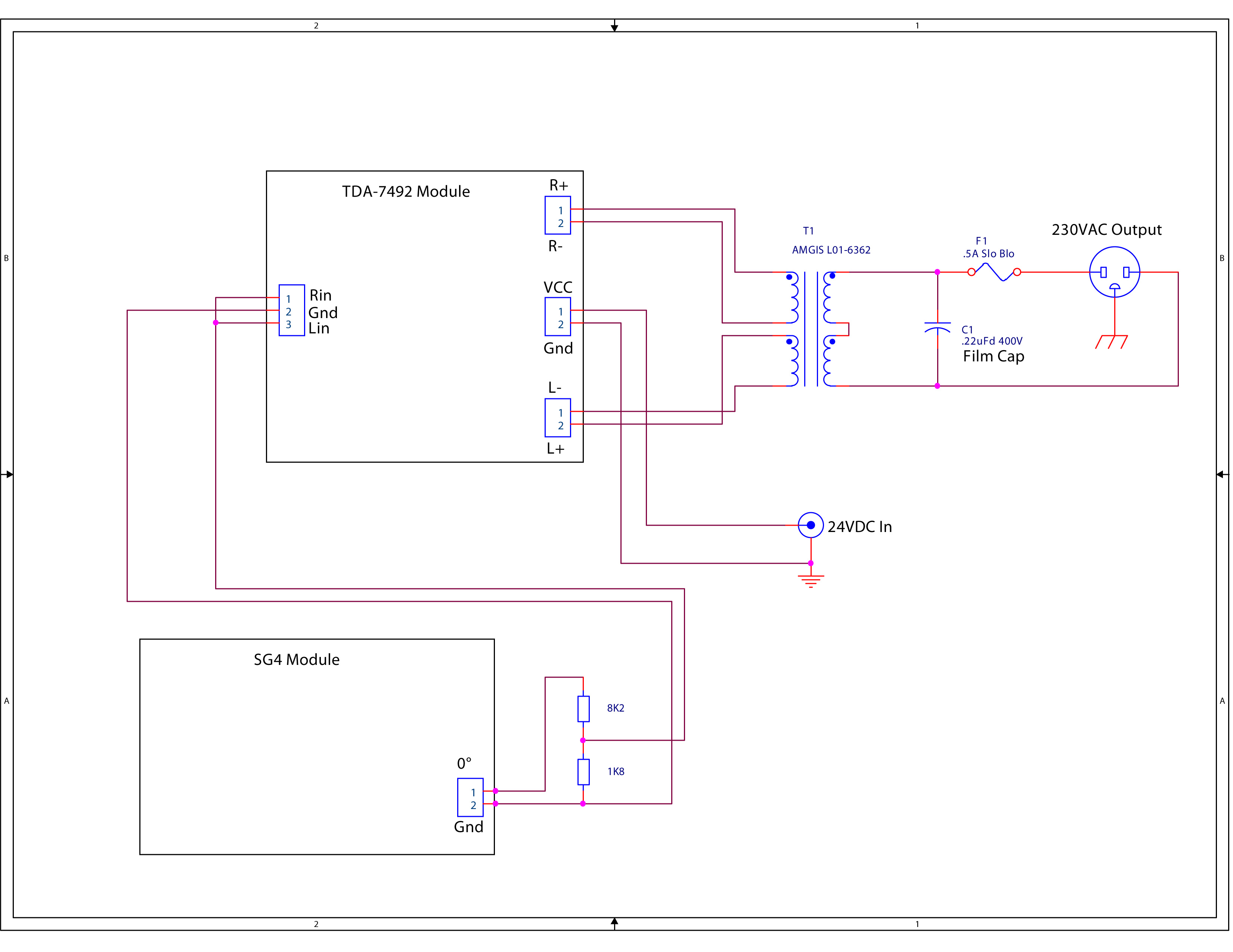
I am using a TDA7492 power amplifier (The one recommended here) to feed the output transformer 2x12V secondaries and 230v primary winding (230V, 35VA).
My idea was to use the ability to decrease the voltage to approximately 200volts to my Garrard so that I can lower vibrations of the motor. I can see now that the output voltage fluctuates from 195 to 210 volts every 5-6 seconds and as a result my speed is inconsistent.
Measuring on the output of the amplifier I am getting the same fluctuations of 11,3 to 12volts AC and probably this is the reason to have the same voltage inconsistent on the output of the transformer where the deck connects.
I have stable 23,9volts DC power to the amplifier and exactly 12 volts DC on the SG4 input.
Decided that probably the cheap power amp is faulty, purchased another one. After the installation I get the same fluctuations in voltage both in the amplifier output and on the output of the step-up transformer. What possible newbie mistake I made or the fluctuations in the voltage are normal? The schematic I used for the wiring is this one:
Long time reader only here.
I bought a SG4 chip and a bare PCB two years ago. The lock-down left me with a time required to finally build the project to be used with my Garrard 401.
I have completed the project and it worked from the first try thanks to the great instructions of the owner of the project.
I am using a TDA7492 power amplifier (The one recommended here) to feed the output transformer 2x12V secondaries and 230v primary winding (230V, 35VA).
My idea was to use the ability to decrease the voltage to approximately 200volts to my Garrard so that I can lower vibrations of the motor. I can see now that the output voltage fluctuates from 195 to 210 volts every 5-6 seconds and as a result my speed is inconsistent.
Measuring on the output of the amplifier I am getting the same fluctuations of 11,3 to 12volts AC and probably this is the reason to have the same voltage inconsistent on the output of the transformer where the deck connects.
I have stable 23,9volts DC power to the amplifier and exactly 12 volts DC on the SG4 input.
Decided that probably the cheap power amp is faulty, purchased another one. After the installation I get the same fluctuations in voltage both in the amplifier output and on the output of the step-up transformer. What possible newbie mistake I made or the fluctuations in the voltage are normal? The schematic I used for the wiring is this one:
Are the input levels to the amp module steady or do they fluctuate as well?
What are you using for the amplifier DC supply? Is it a regulated output (switch mode power supply) or unregulated (linear power supply)?
Does the output voltage fluctuate with the turntable disconnected (no load)?
What are you using for the amplifier DC supply? Is it a regulated output (switch mode power supply) or unregulated (linear power supply)?
Does the output voltage fluctuate with the turntable disconnected (no load)?
- Home
- Source & Line
- Analogue Source
- 60 WPC Amplifier for DIY Turntable Motor Drive