The DC drops to 0.5 to 0.6V which seems to be too much for Nigels amp.
Fuses blow right away. I have a spare TDA7492 module which I could put in instead but didn't want to mess with costly power supplies.
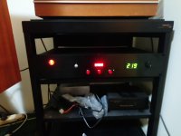
On a more positive note I should have posted pictures of my SG4 build a long time ago.
Regards,
kffern
Fuses blow right away. I have a spare TDA7492 module which I could put in instead but didn't want to mess with costly power supplies.
On a more positive note I should have posted pictures of my SG4 build a long time ago.
Regards,
kffern
Attachments
My apologies, but I didn't read all 89 pages of this and a search didn't reveal what I was looking for.
Would this be the right thing to use on a Pro ject RPM 5.1 turntable (instead of buying a Speed Box or whatever it is that they sell)?
The SG4 is just the sinewave generator portion. The RPM 5.1 uses a 16VAC motor so you would need an amplifier and output transformers to produce 115VAC that will drive the Pro-Ject 16V wall wart.
The first page of this thread has links to amplifier projects that can be used with the SG4.
The DC drops to 0.5 to 0.6V which seems to be too much for Nigels amp.
Fuses blow right away. I have a spare TDA7492 module which I could put in instead but didn't want to mess with costly power supplies.
I should have added in my previous post that the feedback circuit is AC coupled so the gain is 1+R20/R21 at AC frequencies; at DC, the gain is unity. The 3dB point in the gain rolloff is ~2.34Hz.
Try using a pair of TDA7391 bridge amps on 24VDC supply. TDAs have fixed gain of 30dB, so pad down outputs of SG4. Run one SG4 out phase to BLU(TDA1 out+) and WHT(TDA1 out-), second SG4 at 90 degree phase to RED(TDA2 out +) and YEL (TDA2 out -) wires of Pro-Ject 16VAC motor. Adjust as needed for 16 Vrms across each motor winding. Total power is not quite 2watts, << than TDA rated 35watts. Use heat sink. Very quiet in my opinion.
Hi all,
First of all, thanks Bill for this wondering project, and Ralph for handling the shipping internationally. I have a few questions that I hope to get some help on..
I''ve just hooked everything up after putting this in my storeroom for about 2 years.. (Been too busy). I've encountered several issues. Hope someone can offer some advise.
My SG4 works perfectly without the encoder, but with the encoder connected, when I try to turn up, it will only work if i turn it very slowly. When I increase the speed slightly, it'll start to adjust down and it'll start running very fast all the way down. (I know this has been asked in the forum as well, but I am still confused..) I measured the 3 resistors that's supposed to be 10k resistors, and R3 was showing around 3.3k instead. So should I replace this 3.3kohm resistor to a 10kohm resistor?
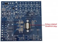
My SG4 is also fed to a TDA8950 amp bridged in mono 300w x 1 powered by a 15-0-15 transformer. stepped up with a 12-0 to 240v. At the moment, when I turn the volume knob somewhat half way, I manage to get 230v. But one step down would be 180v. I wonder what potentiometer should I change it to if I wish to have a more linear change in my output voltage maybe by 1-2v increments or if not possible 5-10v increments?
This unit is powering my thorens td-150, which is running at 33.7rpm stock and I'm very happy with with the speed controller, however the rpm still varies 33.4 to 33.3 (could be mechanical issues such as bearing wear etc) but i'm very happy with this controller as everything used to sound higher pitched before this! I remember sellinco L75 as the speed just isn't stable and you can hear as tho the pianos are doing vibratos and i ended up settling down with my quartz locked DD kenwood (33.33rpm spot on stable). Anyways, sorry for going off tangent, would I be getting better speed results if I were to feed in 2 phase straight into my thorens td-150 motor instead of relying on the phase invert capacitors in my td150? If yes, how should i wire it up?
Should I also use slow-blo 1A fuse at the output and 0.5A at the input with this configuration? Would be helpful if someone can enlighten me on the math..
Thanks!
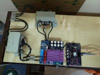
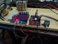
I've attached an image of my wiring. It's all temporary at the moment and I have not found a SPST switch yet. I intend to solder a AC voltage meter at the output and well as the snubber cap later on.
First of all, thanks Bill for this wondering project, and Ralph for handling the shipping internationally. I have a few questions that I hope to get some help on..
I''ve just hooked everything up after putting this in my storeroom for about 2 years.. (Been too busy). I've encountered several issues. Hope someone can offer some advise.
My SG4 works perfectly without the encoder, but with the encoder connected, when I try to turn up, it will only work if i turn it very slowly. When I increase the speed slightly, it'll start to adjust down and it'll start running very fast all the way down. (I know this has been asked in the forum as well, but I am still confused..) I measured the 3 resistors that's supposed to be 10k resistors, and R3 was showing around 3.3k instead. So should I replace this 3.3kohm resistor to a 10kohm resistor?
My SG4 is also fed to a TDA8950 amp bridged in mono 300w x 1 powered by a 15-0-15 transformer. stepped up with a 12-0 to 240v. At the moment, when I turn the volume knob somewhat half way, I manage to get 230v. But one step down would be 180v. I wonder what potentiometer should I change it to if I wish to have a more linear change in my output voltage maybe by 1-2v increments or if not possible 5-10v increments?
This unit is powering my thorens td-150, which is running at 33.7rpm stock and I'm very happy with with the speed controller, however the rpm still varies 33.4 to 33.3 (could be mechanical issues such as bearing wear etc) but i'm very happy with this controller as everything used to sound higher pitched before this! I remember sellinco L75 as the speed just isn't stable and you can hear as tho the pianos are doing vibratos and i ended up settling down with my quartz locked DD kenwood (33.33rpm spot on stable). Anyways, sorry for going off tangent, would I be getting better speed results if I were to feed in 2 phase straight into my thorens td-150 motor instead of relying on the phase invert capacitors in my td150? If yes, how should i wire it up?
Should I also use slow-blo 1A fuse at the output and 0.5A at the input with this configuration? Would be helpful if someone can enlighten me on the math..
Thanks!
I've attached an image of my wiring. It's all temporary at the moment and I have not found a SPST switch yet. I intend to solder a AC voltage meter at the output and well as the snubber cap later on.
Attachments
Last edited:
Ensure either output of the rotary encoder does not stay at ground when the knob stops turning, they should only pulse to ground when turned (there are two types of encoders, one pulses both outputs, the other toggles one output between ground and open and pulses the other). The 3K3 shouldn't matter. Make sure there are 0.47µFd caps on the outputs or the contact bounce will cause erratic operation.
The amp appears to have a volume control so you shouldn't need a pot on the SG4 output. If the control is too sensitive, you can add a single series resistor between the SG4 output and the amp input. Start with the same value as the volume control (if it is a 10K pot, use a 10K series resistor).
The TDA8950 can be configured for single ended stereo or bridge output mono; how is your amp configured and how is it connected to the SG4 and the output transformer (Schematic)?
The phase cap on the motor will not affect speed stability. If the speed is unstable, it may be the bearing or belt; make sure the belt is not loose and clean it with IPA if contaminated.
So I set my DMM to continuity test I first placed the probe on CLK and and second on GND. It pulses to the left and right. But sometimes it stays at ground when I turn to the right or when I apply a slight pressure to the right without turning it..
When I place the probes instead on DT and GRD, it pulses both way left and right and it does not stay at ground even if i apply a slight pressure to the right.
Yes both the caps are there.
Alright, thanks for the tip on the resistor. Will try it!
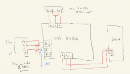
The TDA8950 is configured for bridged output mono (I think). When i tested for continuity, my L+ and L- is connected and both of them are grounded as well so that has let me to think it is bridged output mono (this amp was passed to me by my friend and he has passed on, so i have no idea how did he configured it. so sorry..) (it's blue in colour in the diagram I drew below because I'm not sure as there are no wires connecting it, but my DMM suggests to me they are connected as such)
Also, earlier I tried putting the setting on my turntable for 45rpm running on 50hz. And on that same setting, I tried to dial down the frequency to somewhere around 33Hz in order to run 33rpm and when I did that I heard clicking sound (i'm guessing the amp is clipping?) and when I measure the outputs, it's no longer 230-240volts. It runs everywhere and the turntable stops functioning. This problem stops once I start adjusting the frequency higher and everything runs stable.
Also both the transformers are 60va given that they're 30va one side. One is wired for center tap configuration, the other is wired parallel.
When I place the probes instead on DT and GRD, it pulses both way left and right and it does not stay at ground even if i apply a slight pressure to the right.
Yes both the caps are there.
Alright, thanks for the tip on the resistor. Will try it!
The TDA8950 is configured for bridged output mono (I think). When i tested for continuity, my L+ and L- is connected and both of them are grounded as well so that has let me to think it is bridged output mono (this amp was passed to me by my friend and he has passed on, so i have no idea how did he configured it. so sorry..) (it's blue in colour in the diagram I drew below because I'm not sure as there are no wires connecting it, but my DMM suggests to me they are connected as such)
Also, earlier I tried putting the setting on my turntable for 45rpm running on 50hz. And on that same setting, I tried to dial down the frequency to somewhere around 33Hz in order to run 33rpm and when I did that I heard clicking sound (i'm guessing the amp is clipping?) and when I measure the outputs, it's no longer 230-240volts. It runs everywhere and the turntable stops functioning. This problem stops once I start adjusting the frequency higher and everything runs stable.
Also both the transformers are 60va given that they're 30va one side. One is wired for center tap configuration, the other is wired parallel.
Attachments
Last edited:
If either DT or CLK stay at ground, it is the same thing as pressing and holding the up or down button so the frequency will change rapidly. You either have the wrong type of encoder or it is defective.
Without knowing how your particular amp PCB is configured it will be difficult to troubleshoot. The TDA8950 normally has 2 single ended outputs (out1 & Gnd=one channel, out2 & Gnd= second channel). Bridge operation is accomplished by reversing the input connections to the 2nd input and taking the BTL output from out1 & out2. It's difficult to see a situation where you would ground a (+) output connection. There appear to be 2 input connectors (3 pin and 4 pin). Bridge operation would require a 4 pin connector. Without knowing how your board is configured, you are working in the dark. You need to either find documentation on the amp or find a different one with documentation.
Transformers are designed to operate at 50 or 60Hz; the lower you go in frequency, the worse they will perform and the more stress it will put on your amp. Instead of running 45 RPM at 50Hz and 33 RPM at 37Hz, move the belt to the smaller pulley and the freq for 33 RPM will be 50Hz and 45 RPM will be 67.5Hz.
With a 12V->240V transformer, you will need to provide ~15VRMS to get 240VAC output without load; you will need more than 15VRMS to get 240VAC with a load. 15VRMS is 42.5VPP which will require a minimum of 45VDC or ±22.5VDC supply. 15-0-15 VAC power transformer will give you ±25VDC no load, but only ±21.5VDC with load, so your supply will be marginal; you risk going into clipping just to get 240VAC output.
Attachments
Last edited:
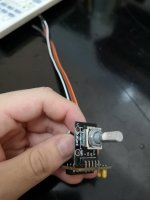
This is a picture of my encoder. Hmm probably it is defective. Maybe it's been sitting for too long, I'll try some contact spray and get back. If it still doesn't work, probably i'll order an encoder and swap it out. I'll order the Bourns PEC11R-4220F-S0012. I think some guys in the forum mention it works
Regarding the TDA 8950 amp. I think it is in single ended mode sorry. I tracked the traces on the PCB, it seems the silkscreen is wrong. It seems the traces for L- mimics the R+ and the traces for L+ mimics the traces for R- so therefore I think L- and L+ silkscreen should be swapped. I think this explains why there is continuity between L+ and R-. So sorry for the confusion.
Ahhh ok. I will use 67.5Hz for 45rpm. Thanks!.
Regarding the transformers, I think it should be okay, as my td150 can startup well with enough torque at 170volts. It even runs ok with enough torque to maintain speed at 100volts. So I doubt I would be using 240vac often at all. Unless in future if I intend to use it for a turntable that needs higher voltage for higher torque, I'll probably swap it out for a higher voltage transformer.
Attachments
Just an update, I've managed to salvage an old alps 10k pot from a old restek busted tuner. I wired it up in between the sg4 output and amp input. Now I can vary the output voltage from my output transformer between 160-230volts (max) linearly. Am very happy with this. Thanks for the idea Bill.
I did encounter a small issue, when the output tranny is giving out about 230 volts, I am not able to do a cold start at 67.5hz for 45rpm. The motor simply will not startup. May be because of the tranny that goes in to my tda8950 of 15-0-15 may be insufficient like you said, Bill. It only works if I start it up at 50hz and dial it up to 67.5hz for 45 rpm.
Nevertheless I find it runs stable and everything works without issue with the xfer output giving about 200volts. And I can cold start both 33rpm and 45rpm. The amp is also just finger warm. So maybe I'll just leave it like this until in future if I need to power up a stronger motor then perhaps I'll change the tranny to 18-0-18. This is with the wiring diagram I drew up. If I wire my R & L outputs any differently, it does not startup and the amp would go into protection mode.
I measured the input tranny powering my tda8950 and the output tranny powering my turntable both only draws about 4.6mA. That's surprising. It only draws so little current. So i'm thinking to put a 10mA fuse on both input and output trannies.
Next steps would be ordering a voltmeter to wire it up at the output tranny going to my turntable. (would be nice if there are displays that display both voltage and frequency up to 2 decimal at the same time, but I struggle to find any. It would make the chassis front panel work much easier). Would also be ordering a bourns encoder and replace the faulty encoder that I have (contact spray did no help)
Hope the next time I update will be everything completed with the enclosure. Thanks for your help Bill! Sorry for flooding this thread with multiple posts.
Attachments
If you are tying both output channels together directly, that may be what is causing the shut down on a cold start. If there is any difference in amplitude or phase, the outputs will fight each other. Normally, there should be a low value resistor (~1-2Ω) in series with each output before they are tied together, but this will also reduce your output level.
You could also run the amplifier in bridge mode (one output to each side of the output xfmr) by inverting the phase of one of the inputs (see pdf diagram in my previous post). This effectively doubles your supply voltage so you won't have any problems with clipping. Looking the the PCB traces, the 4 pin connector is for doing this, but it may bypass the volume control (difficult to tell from the traces).
4.6mA doesn't sound right. I would stay with 0.5A fuses. You can compute the current draw by the power rating of the motor: I=P/V. For a 10W motor at 115V: 10/115=~87mA.
I managed to find the wiring diagram for BTL mode for my amplifier. Found it in a french website.
I tried the said configuration and it's worse somehow. I also tried inverting the inputs and it's worse. I could never get the output transformer to output more than 170v. Any more beyond that the amp starts clipping. Also, it seems connecting the signal input to the 4 pins will have the volume control work just fine.
So I just revert back to my old configuration. Very confused... Maybe this amplifier just isn't suitable or faulty somewhere.
I read from another forum that this thorens td150 motor is only 2W. so 2/230 = that's about 8.7mA.
Looking at the Td150 service manual it appears that the motor is a 115v unit, with an additional resistor (5k6) in series to run it on a 230V supply.
It might be worth removing the resistor and swapping your output transformer wiring to series instead of parallel, thus 24:240. this should reduce the load on the amplifier, especially at startup.
It might be worth removing the resistor and swapping your output transformer wiring to series instead of parallel, thus 24:240. this should reduce the load on the amplifier, especially at startup.
Here is the link that shows how to connect BTL mode
FX-AUDIO M-DIY TDA8950 Class D Amplifier Board 2x170W 300W BTL 4 Ohm - Audiophonics
Ralphfcooke, that sounds like a brilliant idea. Will try that when I get back from work and see if it works! Thanks! Will report back.
FX-AUDIO M-DIY TDA8950 Class D Amplifier Board 2x170W 300W BTL 4 Ohm - Audiophonics
Ralphfcooke, that sounds like a brilliant idea. Will try that when I get back from work and see if it works! Thanks! Will report back.
- Home
- Source & Line
- Analogue Source
- DIY 4 Phase Sinewave Generator for Turntable Motor Drive