My idea to start the Roadrunner up, if I manage to power it from inside the case, would be to wire another momentary switch in parallel with its on board switch and run the leads to mount the secondary switch on the front panel.
You could power the RR from the 12VDC output of the MA-3D with no problem.
You probably don't need to parallel the power switch for the RR, the one on the PCB is a bit redundant. The RR will go to sleep and blank the display automatically after 5 minutes of inactivity and will come back to life when the platter starts turning again. The switch is just to force it into/out of sleep mode.
A SPDT switch between the SG4 and MA-3D would be the best location to reverse the motor drive.
A fuse may be redundant as well, since the wall wart has a 1A current limit and shuts down if it is exceeded. If you want to add one for safety concerns, a 1A slo-blo would be appropriate.
Last edited:
My SG-4 fired up nicely initially standalone, thereon with Arduino encoder added on later.
My observations were:
1) Arduino encoder rotational direction isn't correct, Turning Clockwise was freq down and vice versa. I swapped the wires. I'm guessing the encoder board wire designation marking is an error. Can't be anything else.
Someone else reported the same problem, most likely due to a different switch than I used originally; no problem to just swap wires.
2) 3 tact switches must be installed to engage voltage, factory and phase settings.
Yes, this is important.
3) With 3rd party 12VDC wall wart (from some defunct modem) peak voltage at around 16-17VDC, the LM7805 regulator feels finger hot with a little heat sink since I have these little thingys as spares.
The wall adapters that I call out in the BOM are SMPS types and are regulated at the rated voltage. If you use an unregulated type, the no load (or light load) voltage will be higher. If you use a higher voltage wall wart (or an unregulated one), it may be necessary to add a heat sink to the SG4 regulator.
4) I used an unbranded China made 7 segment and had to carefully wire it up to its own pin assignment. I learned different makes of 7 segment displays are with different pinout (reckon there's no set standard), its imperative to check and plot display pinout on its own datasheet to match the original Liteon display pin assignment. I'm not sure, but the display I'm experimenting with now seems a little glaring or brighter. I thought I'd like it a little dimmer, guess I may have to replace all those 330ohm dropper resistors later on. Toying in my mind for a larger 10mm display. I can't easily buy any Lite-on display where I live. Mouser or Digikey impose minimum quantity for any free shipping at my region.
Almost none of the displays will have the same pin out, even from the same mfr. I found it easiest to make a chart and list each pin of the display and the PCB pins for the Liteon part in the BOM and another column for the new display that you must "translate".
Also, be aware the wires in a ribbon cable with an IDC connector do not go to pins 1-2-3..etc. They connect to pins 1-16-2-15-3-14...etc., so if you solder the wires to the display (or socket) directly, you must take this into consideration.
Regarding brightness, changing the resistors will have little to no effect. LEDs are dimmed by changing the duty cycle to them at normal voltage. The easiest way to reduce brightness is with the use of a neutral density window of plexiglass. They make them in a number of shades of darkness and they are very effective (the RR/Eagle use this, otherwise they would be very bright).
5) I'm hoping Bill would take note of a future option to include through hole solder pads for 5 encoder wires to SG-4 pcb.
If I had thought of this in the beginning, it would have been easy to add, but there is no room on the SG4 to include another thru-hole IC without making it larger.
Last edited:
Man, don't rip apart the RoadRunner! If you're doing DIY, just build your own tach with an Arduino (Digital Tachometer for record player (LCD display)). You could sell off the RoadRunner to someone with no DIY skills for many times the cost of the parts of an Arduino-based DIY tach, and you'd both have something excellent.I have a Roadrunner. It would be nice to integrate it into the same chassis as the SG4 and MA3.
Looking at Chromenuts' SG4, it is not necessary to have 4 wires for each momentary switch (up/dn/stby). The switches have 4 pins, but each switch has 2 grounds in parallel and 2 outputs in parallel.
You can do the connections for all three switches with 4 wires:
Common Ground for all switches (1) [same as power ground]
Up (1)
Dn (1)
Stby (1)
You can do the connections for all three switches with 4 wires:
Common Ground for all switches (1) [same as power ground]
Up (1)
Dn (1)
Stby (1)
Hi Bill
Thanks for all the feedback.
Being able to power the Roadrunner off the 12V supply and have it automatically start up will simplify things.
I should have known the wiring for the tactile switches could have been simpler. I had tested them and knew they had two parallel circuits, but never bothered to analyze what they were doing on the board.
The switch wiring should have been obvious from the image you posted of the hook up points for the rotary switch. I decided to skip the rotary switch for now and just use the tactiles because my turntable project has dragged out for so long now.
That's also the reason I don't want to take on building a DIY Tach now either. I've had an interest in the Arduino for a while, and had considered picking up the Uno to convert my Mill to CNC. It's just a case of too many ideas/projects and not enough time.
I just want to listen to my records again at this point.
@Packgrog...I don't have any desire to butcher the RR. As a matter of fact, if I had been able to use my Falcon and RR with the 3 phase motor and been able to retain the higher resolution automated speed control I would have been very happy. I'll be trying to integrate it into my controller case with minimal or no modification if possible. Anything I have to do will be easily reversible and leave little to no traces.
Have anyone tried a camera gimbal motor to drive a turntable?
AX-GM2212-72Kv Gimbal Motor for 200~500g Camera's
AX-GM2212-72Kv Gimbal Motor for 200~500g Camera's
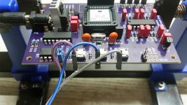
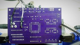
I found a practical solution, may not be the very best but good for bench test and further experimentation. I soldered some right angled pin headers for plug in connection to the rotary encoder. Much earlier I soldered wires direct to the board but not having the best wires on hand till now, they could break off easily. I shopped for these quick connect ribbon cables from local Arduino hobby shop which have all sorts of these hardware for the DIY'er. I was very careful soldering the pins and ensuring they're quite secure and no short circuit anywhere.
Just to satisfy my curiosity, I bought another alternative Arduino Keyes encoder to try out (actually needing it for another SG-4). I still had to swap the up, down wires to match. No problem at all, I'll leave it at that.
Meanwhile I powered the SG-4 with a proper LM317 PSU adjusted for exactly 12VDC, the onboard 7805 with heatsink is normal, that's the best. Lesson learnt, don't use those 12VDC wall warts which are 15VDC or more P-P.
Attachments
Last edited:
Just finished the SG4 and MA-3D combo. For power supply i used LT1084 for regulation. The BLWS231S-24-2000 motor fitted nicely into my VPI Aries housing and managed to glue the two pulleys together, in order to have dual belts. Everything works fine and it is a nice upgrade from the Hurst motor.
I would prefer a little less bearing noise and I have order some ceramic ABEC7 bearings to replace the stock motor ones, as another member did already here.
Thank you again Bill for the excellent project!
I would prefer a little less bearing noise and I have order some ceramic ABEC7 bearings to replace the stock motor ones, as another member did already here.
Thank you again Bill for the excellent project!
Attachments
![IMG_20171207_191501[1].jpg](/community/data/attachments/603/603480-90da6b5de848f34aefc83de269705302.jpg)
![IMG_20171208_200337[1].jpg](/community/data/attachments/603/603491-d58b16f8f605a47e251aefd3f18cd6e6.jpg)
I would prefer a little less bearing noise and I have order some ceramic ABEC7 bearings to replace the stock motor ones, as another member did already here.
Thank you again Bill for the excellent project!
Excellent! Can you please point out to the post you refer to regarding the other member who replaced the motor bearings?
Thanks!
Excellent! Can you please point out to the post you refer to regarding the other member who replaced the motor bearings?
Thanks!
3 Phase Class D amp for DIY BLDC motor Drive
Thanks!
My understanding is that the post refers to the BLWR motor, is that correct? From your photo it looks like you have the BLWS?
Last edited:
Thanks!
My understanding is that the post refers to the BLWR motor, is that correct? From your photo it looks like you have the BLWS?
I think he has both motors, you could ask him for more details if you want.
Hi Gents, go and take a look at the Boca Bearings website. They have a range of bearings including one that has SiliconNitride balls. Might be exactly what you are looking for. I got a few Si3N4 balls from them to play around with in my TD124s. The 6.35x19x6 bearing is unfortunately only in chrome steel but may do the job. Kevin
P.S. These bearings from Boca are really of a high quality, and are used extensively in RC models, roller blades, fishing reels, robotics etc.
P.S. These bearings from Boca are really of a high quality, and are used extensively in RC models, roller blades, fishing reels, robotics etc.
Last edited:
Low noice bearings
Maybe a high tech polymer bushing bearing would be the best solution?
https://www.igus.co.uk/iglidur/cylindrical-bearing
Maybe a high tech polymer bushing bearing would be the best solution?
https://www.igus.co.uk/iglidur/cylindrical-bearing
Hi Gents, go and take a look at the Boca Bearings website. They have a range of bearings including one that has SiliconNitride balls. Might be exactly what you are looking for. I got a few Si3N4 balls from them to play around with in my TD124s. The 6.35x19x6 bearing is unfortunately only in chrome steel but may do the job. Kevin
P.S. These bearings from Boca are really of a high quality, and are used extensively in RC models, roller blades, fishing reels, robotics etc.
I can say positive things about boca too. On one project , I contacted them for advice and they took a very active interest into what I was doing. It's good to know that some companies still value customer service. It's not quite up to the high standards Bill is showing here though
")
This amp might be a little over the top but still nice.
Sure Electronics AA-AB35281 3x200W Class D Audio Amplifier Board - T-Amp
AKA: WONDOM 3 X 200W Class D Audio Amplifier Board - T-AMP
Sure Electronics AA-AB35281 3x200W Class D Audio Amplifier Board - T-Amp
AKA: WONDOM 3 X 200W Class D Audio Amplifier Board - T-AMP
I use a SMPS on all of our commercial products with no problems. They can be more sensitive to overloads, shutting down at the first sign of trouble, but with careful design, this becomes a non-issue. I'd leave at least 3dB of headroom (if your amps require 25W, use at least a 50W power supply).
On the positive side, they provide a well regulated DC output, which makes holding constant voltage at the output of the xfmrs much easier. They are virtually free of power supply ripple which linear supplies can suffer from, especially if not regulated. SMPSs are also much smaller and very efficient (green); in combination with a class D amp, this makes a huge difference: A class AB amp supplying a 25W motor will consume 50W and require a 100W supply. A class D amp supplying a 25W motor will consume 26W and require a 50W supply.
SMPSs are usually universal input (100-260VAC 50/60Hz) so they don't have to be reconfigured for different wall power. In the past, people stayed away from them, as some of them (poorly designed) were electrically noisy. The design of these supplies has progressed to the point where this is no longer an issue, even on cheap supplies.
Sure Electronics AA-AB35281 3x200W Class D Audio Amplifier Board - T-Amp
AKA: WONDOM 3 X 200W Class D Audio Amplifier Board - T-AMP
Unfortunately, the amp is configured for bridge output (BTL) so it would not work in this application.
- Home
- Source & Line
- Analogue Source
- DIY 4 Phase Sinewave Generator for Turntable Motor Drive