I see the MK-154 amps are no longer available. There are quite a number of TDA7293 amps on e-Bay and they are just as low cost:
2Pcs TDA7293 100W Digital Audio Amplifier Board AC 12V-50V Mono Single Channel | eBay
You would need to identify the 2 resistors that are used to program the gain and modify them so the gain is ~13.6-13.8.
The attached diagram shows a typical application. The gain is programmed by R11 and R12 and equals: 1+R11/R12. In this case the gain=33.3 or 30.5dB. To change to gain to 13.75, change R11 to 8.67K.
Attachments
Last edited:
Its a case of building SG-4 to output 24VAC feed to your Rega RP8 that would make it work nicely. I'm almost sure Rega does not offer any external controller with variable frequency control, its a regenerated fixed output.
You can generate 24VAC directly using the MK-154 amp as shown in this thread: 60 WPC Amplifier for DIY Turntable Motor Drive
24VAC is ~68VPP. You will need to power the amp with 2x25VAC or a 50VAC secondary with a center tap. That will provide ~±35VDC which will allow 70VPP without clipping.
Instead of adding 2K2 in parallel with the 22K resistors, put 10K in parallel with the two 22K resistors as shown in the thread. This will give you a gain of ~13.75 and with 5VPP from the SG4 will provide 68.75VPP or 24.3VAC at the output.
You will not need a transformer between the motor and the MK-154. The output is centered a zero VDC and can drive the 24VAC Rega motor directly.
I see the MK-154 amps are no longer available. There are quite a number of TDA7293 amps on e-Bay and they are just as low cost:
2Pcs TDA7293 100W Digital Audio Amplifier Board AC 12V-50V Mono Single Channel | eBay
You would need to identify the 2 resistors that are used to program the gain and modify them so the gain is ~13.6-13.8.
The attached diagram shows a typical application. The gain is programmed by R11 and R12 and equals: 1+R11/R12. In this case the gain=33.3 or 30.5dB. To change to gain to 13.75, change R11 to 8.67K.
Thanks a lot! I´ll follow your instructions.
Billy
My bad I didn´t notice the user jcastellano already asked exact the same question. Sorry about that.
I bought the TDA 7492, a DC Linear Converter Buck Step Down LM317 from Alixpress a couple of weeks ago, as I was planning to use it single phase on my former TT. Now, with the new TT and it´s 24V motor, the idea is to use dual phased.
I intend to use the same 24V DCC power suppply to feed both the SG4 and the TDA 7492, using the LM317 to get the 12V to the SG4.
Will it work if I make the required gain modifications what will be the max power requirements for the 24DCC power supply?
I apologize asking so many questions. This is my first attempt to build an electronic device. I´m a noobie on this matters..
Once again, thanks a lot for all support.
The TDA7492 will not work. 24VAC is 68VPP. The TDA7492 is a bridge tied load (BTL) amp and can only produce the equivalent of 48VPP or 17VAC. Since is BTL, you would also have to separate the common return on the motor.
Ok, many thanks for that!
I found the TDA7293 here in Brazil. Will buy 2 of them and try to make the gain adjustment as per your instructions.
A wonderfull New Year´s Eve to all of You nice people in this forum.
Billy
Ok, many thanks for that!
I found the TDA7293 here in Brazil. Will buy 2 of them and try to make the gain adjustment as per your instructions.
A wonderfull New Year´s Eve to all of You nice people in this forum.
Billy
Note well that TDA7492 is a Class D and TDA7293 is Class AB, you'd need to consider size and space for proper heat sink for 7293 type. Its because I'm trying to compact my upcoming controller with less bulky parts and smaller chassis that I look to suitable Class D modules to implement here.
Last edited:
Note well that TDA7492 is a Class D and TDA7293 is Class AB, you'd need to consider size and space for proper heat sink for 7293 type. Its because I'm trying to compact my upcoming controller with less bulky parts and smaller chassis that I look to suitable Class D modules to implement here.
Thanks, buddy. I'll make sure It will have proper room for breathing.
Hi all -- Does anybody have a spare SG-4 board they'd be willing to sell? I'm having trouble ordering from OshPark for some reason--the site is requiring me to sign up for an account, but then requires response to a "confirmation" email that hasn't been sent, even after repeated attempts. I wanted to order the full set of boards for use with the Anaheim Automation motors, but it seems I'm stuck. Any help much appreciated. Thanks!
Hello,
I managed to assemble the SG4, initial tests whith great results!
Used the monophase, 230V / 50 Hz setup, just like a photo I saw here with a Lenco motor.
The AC voltage oscilated from 233.2V to 233.4V, and the frequency was 100% steady, 50Hz or 67.5Hz, any .01 Hz change on the SG4 panel reflected the same way at the Fluke, I was really impressed with the precision and stability.
Then, after about 20-30 minutes, I changed the switch from 45 rpm back to 33 rpm and it stopped working!
The AC outlet droped to about 5 up to 9 V then ~ 5 V AC and the frequency was crazy, jumped up to 700 Hz then down to 60Hz then higher... never an exact value.
The SG4 board appears to be working fine, at least all display functions and buttons show a normal behavior. Also, the failure was completely silent, no "boom"...
At least, I´m sure that there is no assembly error, because it worked perfectly during the
initial minutes.
Tomorrow I will measure the voltage and frequency at the 0° / GND pins on the SG4 output, then after the resistor bridge at the TDA input, at the TDA output and finally at the
transformer output.
My guess is that the cheap TDA7492 is the faulty one...
Should the frequency be the same (50 Hz, i.e.) at all these points?
Should the frequency be the same (50 Hz, i.e.) at all these points?
Yes.
You should always use the SG4 to switch between speeds and go to Stby to stop the motor. If you use a switch to interrupt power to the motor, the amp can shut down.
The amps also have very good overload protection; it is difficult to damage them, but they are quite sensitive and will shut down if they see a potentially difficult load.
Thanks Bill for the prompt answer!
Yes, it´s back working fine, but I still don´t know exactly what was the problem...
After re-testing all voltage and frequency values, I found no errors at all, everything looked normal, then re-assembled it and now it´s 100% exact again!
Measured results:
SG4 Out at 0° / gnd : 2.52 V DC / 1.78 V AC / 50.00 Hz
TDA in : 452 mV DC / 301 mV AC / 50.00 Hz (monophase)
TDA out : R - 14.4 V / L - 14.2 V
Rear outlet: ~ 233 V and rock steady 50.00 Hz
Possible reasons for the problem:
- TDA heat-sink badly attached that results in overheat;
- Very low load at the end of TDA, since it was just the transformer and the multitmeter;
- I must have touched both the 33/45 and power switches at the same time, they are at the rear panel;
This won´t happen anymore, the 33/45 switch is now a jumper just like the 50/60 Hz one.
I don´t have 45 rpm LP´s at the moment, and will use the removed switch hole to the tachometer sensor connector.
Last edited:
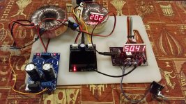
This is the latest rigging up of everything under test and putting it through its paces.
I added an output AC voltmeter and buck converter to power the SG-4 module. The buck converter module is far cheaper and possibly a better bet than good ole LM317 to power the SG-4. I really hope its reliable throughout.
I think buck converters are a great choice for DC step down. Input is 33V adjusted to 12Vdc sourced from the Linear rectifier board that also power the TDA7498 amp.
I'm using massive sized transformers just for test for these are the only ones I have lying around and suitable. Actual ones to be used are in process of being purchased. Currently on back order.
At this moment, there's a voltage drop of 2-3VAC with motor load connected at the output. Not a problem.
So far so good. I sensed a more superior sound from the table. There's no looking back. This project must be finished.
Attachments
Last edited:
Hi Robin,
The thanks for the SG4 should be directed to Bill (Pyramid). I simply act as middle man to deliver the chips to people who would like to build the SG4 (outside of the USA).
Great testing setup.
Could you please share what is the display in the picture. Can I also kindly ask you to give the pi out translation and which pin of the display goes where on the Pcb. This will be greatly appreciated.
Thanks in advance.
Best regards.
Great testing setup.
Could you please share what is the display in the picture. Can I also kindly ask you to give the pi out translation and which pin of the display goes where on the Pcb. This will be greatly appreciated.
Thanks in advance.
Best regards.
Awww!...I threw out that pinout work sheet I scribbled the pin direction used as reference during the wiring up process. I adapted and used Arduino hookup wires Female to female type, plugged into the SG-4 directly to the LED display. Its now plug n play for convenience. The only soldering is male pin studs on the pcb to plug n play.
I will print another and post it here later on.
The display I used is an unbranded China made 0.56" 4bit Red common cathode which I can easily find locally for 2 bucks. For now, as long as it works, I'm happy about it. I can always replace to some better make later on for the aluminum chassis. (which I still trying to figure the best front panel layout). I'm finding 0.56" a bit too large. I may go for 0.36". The suggested 0.28" is too small for my liking.
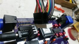
Here are details of wiring up alternative 4bit 7 segment Common Cathode LED display commonly found on Ebay or Aliexpress vendors.
Check the display applying forward bias to Pin 1 & 12 to light up at 1st digit Segment E for pin compatibility as per details shared here.
I matched up my display to SG4 following these pin designations.
Next picture show the use of Arduino hookup wires (not seperated), slightly customed with all in a row arrangement sleeve, marked so that its easily plugged on both sides anytime without mistake. I reckon this is the most practical solution for me at this time. Its possible I could do better with some ribbon connector and IDE type connectors but I couldn't find the right type here in my place. These Arduino wires are a little stiff but they're functioning well and won't break.
Meanwhile, about the TDA8950 amp module which was giving me headaches from high DC offset at output to heat issues at the LPF coils to not powering the step up transformers in SE mode. This happen when I apply when the onboard rectified DC voltage is at a high 33-34VDC (thinking this input voltage will optimize the amp power) to the amp circuitry. I've now inputted a 15-0-15 AC into the amp module, resulting in 23VDC at the filters, the LPF is touch warm at idle. It seems normal.
I highly suspect a compromised TDA chip on board or there's something just not right about it and I cannot explain why. When my 12V transformers arrive, I intend to try SE mode to see if it works. If it still doesn't work, its next destination is the bin.
Attachments
Last edited:
Does the SG4 demands at least 12V DC or would it run fine on 9V or 10V ?
I used an adjustable buck converter sourced from amp power supply to power the SG4, preset at 12VDC. Since the circuitry is working on 8VDC and 5VDC, I think 10-12VDC or a little bit more will be just fine. 12VDC should be ideal. Its cheaper and easier to install a buck converter than the hassle of making LM317 regulator on pcb. So far the buck converter runs cool with the SG-4 functioning.
Thanks Coolmaster!
I´m using a similar buck converter as yours, so to keep it safe I was considering adjusting the output to a lower value, like 10V or a bit more, but if the SG4 won´t fry at 13-14V, then it´s better to leave it at 12V.
Also found another option:
MP2307 DC-DC Switching Buck Step-Down Module - ElectroDragon
The maximum input is rated at 23V but may work at 24V and is a lot smaller board if someone needs to assemble it into a small case.
Also, an IMPORTANT ADVICE here: take care when checking the heatsink of the TDA, one of the screws here was loosen and I decided to remove both to see if the thermal compound was ok. I was very gentle but ended up with the whole amp IC pulled off from the PCB, ruining the amp...
Already ordered two of these amps boards, they are cheap but it´s kind of a lotery to buy one that works 100% as it should.
While searching for an alternative to the TDA7492, I considered the TK2050, the board looks better/slim, has a LED that confirms it´s working, the size is exactly the same as the SG4 pcb, making it easy to stack both PCBs on a small case AND it would work on 12V just as the SG4.
JINSHENGDA TK2050 Dual Channel Class T HIFI Stereo Audio Digital Amplifier Board 50W+50W-in Amplifier from Consumer Electronics on Aliexpress.com | Alibaba Group
But then one of the feedbacks showed the same disaster that ocurred to me!
Sometimes they just use a strong glue to attach the heatsink over the IC and don´t fasten the screws properly or simply don´t use any screw at all to secure it over the IC and the PCB.
Last edited:
When I recently recieved 2 amplifier modules, the first thing I checked was the heat sinking and replace the heat sink compound. Also to check if there is anything unusual. I will also check everything else for bad soldering or unusual again, thereon powering it up without signal or load, take measurement for dc offset at the output. Lastly I wont use any glue to adhere the heat sink. Properly tighten the screws will be good to go. Better be safe than sorry. About the buck converter, there is 2 models easily availble to buy locally and so far they're good. I compared mine to bad specimens reported on forums.
What is availble to me here is the 3amp low and higher voltage modules. The lower voltage model works fine for SG4. No issues by accurately adjusting from 9vdc to 12vdc. I'm set on 12vdc for SG4.
What is availble to me here is the 3amp low and higher voltage modules. The lower voltage model works fine for SG4. No issues by accurately adjusting from 9vdc to 12vdc. I'm set on 12vdc for SG4.
- Home
- Source & Line
- Analogue Source
- DIY 4 Phase Sinewave Generator for Turntable Motor Drive