Yes belt drive, and I would like to keep the control functional (it is not 100% functional now, because I removed the speed-change mechanism when I rebuilt the unit a few years ago). Of course it currently operates a small SPST switch which is in series with one power lead, so I assume I would need to replace it with some sort of 2-pole rotary switch. The 33/45 part is easy, but I am looking for a way to accomplish the on/standby switching. I am thinking logic gates, maybe some sort of edge-triggered flip-flops which would send a pulse on either edge, and that pulse could operate a transistor as a switch. How does that rotary encoder thing work for the on/standby?
The other option is to replace the 33/ogg/45 swict with a simple switch for 33/45 and, since I no longer use the original tonearm, use the tonearm lift knob position to hold the speed-adjust/on-off rotary controller.
The other option is to replace the 33/ogg/45 swict with a simple switch for 33/45 and, since I no longer use the original tonearm, use the tonearm lift knob position to hold the speed-adjust/on-off rotary controller.
The rotary switch option uses a quadrature output rotary switch for the up/dn function (a 4013 dual D flip-flop converts the 2 quadrature pulse trains into individual up or down pulses depending on the direction of rotation) and a momentary push switch for the Stby function.
http://www.diyaudio.com/forums/analogue-source/300371-60-wpc-amplifier-diy-turntable-motor-drive.html#post4925753
You still need the momentary push switches for UP/DN on the PCB to access the voltage and phase setting modes.
http://www.diyaudio.com/forums/analogue-source/300371-60-wpc-amplifier-diy-turntable-motor-drive.html#post4925753
You still need the momentary push switches for UP/DN on the PCB to access the voltage and phase setting modes.
Last edited:
Dear Pyramid,
thank you very much for your input.
I did all the tests you advised me and it turned out that the Q2 was faulty. I replaced it with a spare one and now the second segment is working.
I am waiting for the TDA power amplifier to show up and then will start building the controller. I suppose I will have additional question which I will ask as soon as I start assembling it.
Thank you once again for your great product and the constant help you are providing here.
Best regards.
It looks like digit 2 is partially lit (a lower case "t" is barely visible). The other digits appear correctly, so the 7 segment driver (U3 and R10-R17) are all OK. The display is common cathode and Q2 controls when the second digit is displayed (pin 14 of the display is grounded to enable digit 2). If you temporarily short drain to source on Q2 (or short pin 14 of the display to ground), the second digit will be enabled always and you will see an "8" (the second digit will display "S", "t", "b" & "Y" so all of the segments will be lit). If this happens, then the display is OK and the connection from Q2 to pin14 should be OK.
If you have a scope, look at the gate of Q2; you should see a square wave with a period of 20mS and a positive duty cycle of 25% (digit 2 is on 25% of the time). If you don't have a scope, a DC voltmeter should show ~1.25VDC on Q2 gate. Q2 gate is feed directly from pin 24 of the microprocessor. Check that there are no shorts to ground or open circuits from U1 pin 24-->Q2 gate; from Q2 drain-->display pin 14.
The output op-amp has an 8V regulator for a supply; with 7VDC input, you will only get 5-5.5VDC output to U2 opamp and the output signal may be distorted. You should use 12VDC to power the SG4.
Dear Pyramid,
thank you very much for your input.
I did all the tests you advised me and it turned out that the Q2 was faulty. I replaced it with a spare one and now the second segment is working.
I am waiting for the TDA power amplifier to show up and then will start building the controller. I suppose I will have additional question which I will ask as soon as I start assembling it.
Thank you once again for your great product and the constant help you are providing here.
Best regards.
Terrific! Good job troubleshooting....

For ordering/shipping purposes is Canada considered US or ROW? We are physically closer to US than UK, but...
Does anyone have single boards for sale? Do the little encoder boards need to be ordered in sets? Does anyone sell singles? Are twystd and ralphfcooke still the correct sources for uP's?
Thanks.
Does anyone have single boards for sale? Do the little encoder boards need to be ordered in sets? Does anyone sell singles? Are twystd and ralphfcooke still the correct sources for uP's?
Thanks.
Dear Pyramid,
I have just realized that I have forgotten to purchase a PCB for the encoder.
As it is too late now and I am located in Europe it will be very expensive to purchase only the encoder board. As I can see the scheme is simple and only a few components involved, do you think it will be possible to share the drawing (scheme) of it so that i can do it on a small strip-board?
Thank you very much in advance.
Best regards
Last edited:
Thanks Pyramid,
I have successfully finished the encoder board on a test PCB. It is working fine although there is one small issue: When i rotate the encoder clockwise the frequency decreases while turning the knob counter-clockwise the frequency increases.
I have checked the schematics countless times and can't find any mistake. Probably it is something simple i do not see?
Also, turning the encoder fast it can't simulate a long press from the momentary switches. Probably it is only for a fine tune of the frequency?
Thanks.
Best regards.
Thanks Pyramid,
I have successfully finished the encoder board on a test PCB. It is working fine although there is one small issue: When i rotate the encoder clockwise the frequency decreases while turning the knob counter-clockwise the frequency increases.
Either swap the input wires coming from the encoder switch, or the output wires going to the SG4.
Also, turning the encoder fast it can't simulate a long press from the momentary switches. Probably it is only for a fine tune of the frequency?
Thanks.
The only button that has a long press function is Stby, and that should be connected to the momentary push switch of the encoder.
You will still need to access the plus/minus buttons on the SG4 in order to enter reduced voltage mode (minus button pressed while exiting standby) or phase adjust mode (plus button pressed while exiting standby).
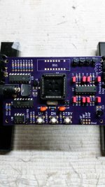
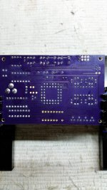
A load of parts arrived today and have started the build. Populated most of the stuff except a few caps which I missed out in the BOM. Later on I'll have to figure the wiring to adapt to another make of 7 segment display as its not pin compatible.
Attachments
Hi!!
I´m traying to find the tantalum capacitors for the encoder board but no lucky here in Brazil... Can I use a 0.47uF x 35V? That´s the only one I can get down here.
Thanks in advance!!
It just occurred to me you are talking about the rotary encoder switch and not the SG-4.
Yes, you can use .47uFd 35V for the decoupling caps on the input to CD4013 IC.
It just occurred to me you are talking about the rotary encoder switch and not the SG-4.
Yes, you can use .47uFd 35V for the decoupling caps on the input to CD4013 IC.
Thanks a lot for this project and the support you provide.
Billy
Hi Bill
I've been working on my table, motor and the SG4 and MA3 for a while. I'm close to powering up, but I have a few questions that will affect how I decide to wire things up for my final assembly.
There are some things I'd like to work into this project if possible.
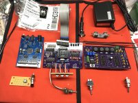
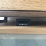
I have a Roadrunner. It would be nice to integrate it into the same chassis as the SG4 and MA3. That way I won't have more wires tangling up under my table where I want to put the controller (pic). Also, not having to deal with another wall wart would be great.
The Roadrunner says it needs a 9V DC input if I remember correctly. It also appears to have a momentary switch presenting ground to a leg on it's processor chip that initiates power up?
I pulled the Roadrunner board out of its case and arranged it next to the others to consider how I might integrate it(pic).
I noticed it uses the the same regulator for its power supply as the SG4. Is it possible to power it by connecting it in parallel with the leads of the SG4 at the MA3 12V DC output without reducing the voltage?
If it cannot accept the 12V DC from the MA3 supply tap, or if the MA3 can't supply the additional current, is it possible to grab the 9V elsewhere on the MA3 or SG4?
I've also wondered, can the wall wart supply enough current for all 3 boards?
Perhaps I would need to reduce the 15V directly off the wall wart for the Roadrunner separately somehow?
My idea to start the Roadrunner up, if I manage to power it from inside the case, would be to wire another momentary switch in parallel with its on board switch and run the leads to mount the secondary switch on the front panel.
Another feature I'd like to integrate would be a switch for reversing the direction of motor rotation to experiment with rim drive. In one of the related threads it was mentioned this could be accomplished by reversing two of the phase wires powering the motor.
I was thinking of adding a DPDT center off switch between the SG4 and MA3 that would allow me to reverse the polarity of the 120 and 240 degree phase wires to achieve this. Would that do the trick?...or perhaps it should be done at the output of the MA3?
Would it be a good idea to have a fuse on the incoming 15V DC supply to the MA3? Could you recommend a proper type (fast?slow?) and rating for the fuse? Unless you feel it's unnecessary?
Any guidance you can offer is greatly appreciated.
Kevin
I've been working on my table, motor and the SG4 and MA3 for a while. I'm close to powering up, but I have a few questions that will affect how I decide to wire things up for my final assembly.
There are some things I'd like to work into this project if possible.
I have a Roadrunner. It would be nice to integrate it into the same chassis as the SG4 and MA3. That way I won't have more wires tangling up under my table where I want to put the controller (pic). Also, not having to deal with another wall wart would be great.
The Roadrunner says it needs a 9V DC input if I remember correctly. It also appears to have a momentary switch presenting ground to a leg on it's processor chip that initiates power up?
I pulled the Roadrunner board out of its case and arranged it next to the others to consider how I might integrate it(pic).
I noticed it uses the the same regulator for its power supply as the SG4. Is it possible to power it by connecting it in parallel with the leads of the SG4 at the MA3 12V DC output without reducing the voltage?
If it cannot accept the 12V DC from the MA3 supply tap, or if the MA3 can't supply the additional current, is it possible to grab the 9V elsewhere on the MA3 or SG4?
I've also wondered, can the wall wart supply enough current for all 3 boards?
Perhaps I would need to reduce the 15V directly off the wall wart for the Roadrunner separately somehow?
My idea to start the Roadrunner up, if I manage to power it from inside the case, would be to wire another momentary switch in parallel with its on board switch and run the leads to mount the secondary switch on the front panel.
Another feature I'd like to integrate would be a switch for reversing the direction of motor rotation to experiment with rim drive. In one of the related threads it was mentioned this could be accomplished by reversing two of the phase wires powering the motor.
I was thinking of adding a DPDT center off switch between the SG4 and MA3 that would allow me to reverse the polarity of the 120 and 240 degree phase wires to achieve this. Would that do the trick?...or perhaps it should be done at the output of the MA3?
Would it be a good idea to have a fuse on the incoming 15V DC supply to the MA3? Could you recommend a proper type (fast?slow?) and rating for the fuse? Unless you feel it's unnecessary?
Any guidance you can offer is greatly appreciated.
Kevin
Attachments
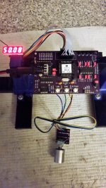
My SG-4 fired up nicely initially standalone, thereon with Arduino encoder added on later.
My observations were:
1) Arduino encoder rotational direction isn't correct, Turning Clockwise was freq down and vice versa. I swapped the wires. I'm guessing the encoder board wire designation marking is an error. Can't be anything else.
2) 3 tact switches must be installed to engage voltage, factory and phase settings.
3) With 3rd party 12VDC wall wart (from some defunct modem) peak voltage at around 16-17VDC, the LM7805 regulator feels finger hot with a little heat sink since I have these little thingys as spares.
4) I used an unbranded China made 7 segment and had to carefully wire it up to its own pin assignment. I learned different makes of 7 segment displays are with different pinout (reckon there's no set standard), its imperative to check and plot display pinout on its own datasheet to match the original Liteon display pin assignment. I'm not sure, but the display I'm experimenting with now seems a little glaring or brighter. I thought I'd like it a little dimmer, guess I may have to replace all those 330ohm dropper resistors later on. Toying in my mind for a larger 10mm display. I can't easily buy any Lite-on display where I live. Mouser or Digikey impose minimum quantity for any free shipping at my region.
5) I'm hoping Bill would take note of a future option to include through hole solder pads for 5 encoder wires to SG-4 pcb.
Its been quite interesting project.
Lee
Attachments
Last edited:
- Home
- Source & Line
- Analogue Source
- DIY 4 Phase Sinewave Generator for Turntable Motor Drive