Pyramid:
Is there a particularly good place on the SG-4 board to tap for the voltage needed to drive a totally unnecessary LED? 5V, 8V, it doesn't matter. I'd like to put an on/off switch on the front panel and for some reason the display, by itself, just isn't enough of an indication the unit will be on.
Dumb, I know.
Regards,
Scott
Pyramid:
Is there a particularly good place on the SG-4 board to tap for the voltage needed to drive a totally unnecessary LED? 5V, 8V, it doesn't matter. I'd like to put an on/off switch on the front panel and for some reason the display, by itself, just isn't enough of an indication the unit will be on.
Dumb, I know.
Regards,
Scott
The input side of the 5V regulator U7 would be a good point. If you are supplying 12VDC to the PCB, you will need a ~1k resistor in series with the LED.
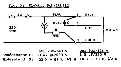
Configuration for a TD-124
I ordered the parts to build an SG-4 for my TD-124 mk II.
It has a single phase motor which has a capacitor on one of the windings.
The diagram is shown below.
Would I connect the 0 degree output to position 4-3 and the 90 degree output to position 1-3?
Since there is only one switch I would need to wire in a relay so I could switch both 0 and 90 degree outputs together.
Alternatively would I just leave the cap in place and connect the 0 degree output to position 4-3 ?
Look at the wiring diagrams in at the end of the original post in this thread:
http://www.diyaudio.com/forums/anal...-wpc-amplifier-diy-turntable-motor-drive.html
For single phase operation, use the first wiring diagram and connect the transformer pins 1 & 3 (purple line) to pin 3 on your motor. Connect transformer pins 2 & 4 (orange line) to pin 4 on your motor. Leave the phase capacitor between pins 1 & 4 of the motor. You do not need a motor switch; it can be removed or left in the on position. Start and stop the motor with the standby switch on the SG-4.
For dual phase operation, use the last wiring diagram and connect transformer pins 1 & 3 on BOTH transformers (purple lines) to pin 3 on your motor. Connect the 0° transformer pins 2 & 4 (orange line) to pin 4 on your motor. Connect the 90° transformer pins 2 & 4 (orange line) to pin 1 of the motor. Remove the phase capacitor from the motor. You do not need a motor switch; it can be removed or left in the on position. Start and stop the motor with the standby switch on the SG-4.
There is high voltage present on the output of the transformers. If you are not familiar with working with high voltage and high power, do not attempt this yourself; get technical help from someone with electrical experience. If you are unsure about what you are doing, do not guess, get someone local to verify your wiring.
I ordered the parts to build an SG-4 for my TD-124 mk II.
It has a single phase motor which has a capacitor on one of the windings.
The diagram is shown below.
Would I connect the 0 degree output to position 4-3 and the 90 degree output to position 1-3?
Since there is only one switch I would need to wire in a relay so I could switch both 0 and 90 degree outputs together.
Alternatively would I just leave the cap in place and connect the 0 degree output to position 4-3 ?
From your diagram it looks like your turntable uses the three phase Papst motor. If this is indeed the case then you will really benefit from driving it with a proper 3 phase supply.
Have a look through this thread to get a handle on what can be done
http://www.diyaudio.com/forums/anal...riving-vpi-synchronous-turntable-motor-4.html

OK, we're mixing things up a little here. The wiring diagram you showed corresponds with the use of the 3 phase Papst motor which I think you found on the Soundfountain website,and unfortunately took a little out of context.
The picture you showed after is of the E50, but the E50 does not have a 0.47uF capacitor between phases, indeed it does not have phases, plural, only 1 phase and the only capacitor is a 0.01uF across the switch contacts.
You need only build a single phase power unit for the SG4 for your your TD124, and the output can be connected directly to the wires that currently conect to your wall socket. You may gain a little extra smoothness from the regenerated power supply, but the main advantage will be the stability
That's an E50 shaded pole induction motor that was standard in the original 124 and the MKII. I have both a 124 and a 124 MKII with this motor, and I also have a 3 phase Papst that I am eventually going to install in my MKII with a 3 phase supply based on Pyramid's board.
The E50 is single phase and requires only one phase, the windings are wired in series. In fact make no modifications to the table's wiring and just use the 0 degree output of the sinewave generator to drive a 50W amp into a good 50VA EI step up transformer. (This what I currently do in a homebrew sine wave source for the MKII)
The E50 is single phase and requires only one phase, the windings are wired in series. In fact make no modifications to the table's wiring and just use the 0 degree output of the sinewave generator to drive a 50W amp into a good 50VA EI step up transformer. (This what I currently do in a homebrew sine wave source for the MKII)
Ralph and Kevin:
Thanks for straightening me out")
I'll plan on a single output with a 50W amp and 50VA transformer.
A tangentially related question...
Has anyone tried a 24 V, 3 phase BLDC motor with 3 phase sine wave drive in a TD-124 ?
In reading the "optimally driving a VPI" thread it seems like this might be fairly straightforward alternative to the unobtainium Pabst motors.
Could one drive the 24 Vdc motor directly from the amplifiers directly and avoid the transformers ?
Thanks for straightening me out
I'll plan on a single output with a 50W amp and 50VA transformer.
A tangentially related question...
Has anyone tried a 24 V, 3 phase BLDC motor with 3 phase sine wave drive in a TD-124 ?
In reading the "optimally driving a VPI" thread it seems like this might be fairly straightforward alternative to the unobtainium Pabst motors.
Could one drive the 24 Vdc motor directly from the amplifiers directly and avoid the transformers ?
Could one drive the 24 Vdc motor directly from the amplifiers directly and avoid the transformers ?
[url]http://www.diyaudio.com/forums/analogue-source/288730-3-phase-bldc-motor-turntable-use-13.html#post5061406[/URL]
Yes you could drive such a motor directly, but you'd need amplifiers that swing more volts, a 24vDC motor would need 24 x 2.8 = 68V p-p, and the amplifiers would need to be single ended unless you can separate the windings completely.
Since these are not true "DC" motors (the DC is switched on/off and changes polarity) they do not need that high of drive voltage. The 24V motor I'm using can be driven to rated speed & power (2000 RPM & 12W) with 24VPP (8.5VRMS); the needed drive voltage decreases with lower speed so to drive the motor at 600 RPM only requires 11.5VPP (~4VRMS).
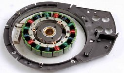
SG-4 to drive an SP-10 MkIII
I just purchased an SP-10 MkIII sans power supply
The Mk III uses a 15 pole, 3 phase motor (picture below)
I also recently purchased an SG4 kit and was thinking I could drive the SP-10 with it using the amp and transformer set up.
The motor supply voltage from the technics service manual shows +/- 32 Vdc going to the motor bridge.
While the SG4 would not have the Quartz PLL It seems like it could run the table without it.
Since it is a 15 pole motor would I need a SG-4 chip programmed for a lower frequency ?
Attachments
Since it is a 15 pole motor would I need a SG-4 chip programmed for a lower frequency ?
The SP10 is a direct drive motor. It will spin at the platter speed or 33 RPM and would most likely need a frequency of <1Hz. No, the SG4 is not suited to drive this type of motor. It is for belt drive tables with 600 RPM motors.
Wasn't sure which thread to post this question in...seeing how it ultimately relates back to using the SG4 I figured here might be best.
When using the SG4 in a multi-phase arrangement, be it 2 phase for AC sync, induction etc. or 3 phase for Papst, BLDC and the like, is it necessary to have a separate power supply to operate each of the multiple amps used for the different phases?
I will end up building more than one version of the SG4 using multiple phases. I would say at least one 2 phase with the possibility of a second and one 3 phase.
The 2 phase versions will use the 7942 amps and I've selected a 60W 24V power module similar to the one shown in the amp thread. I'm wondering if a single 60W module will be sufficient for the two amps, or if separate supplies are required? Perhaps a single higher rated supply is a possibility? I'm trying to figure out if there is a more cost effective way to power the amps in these multi-phase controllers.
No you can run all three amps off of one supply. I'm running three 100 watt mono amps with one 24V 20 amp switching supply. Overkill but cheap enough. I'm running Papst flywheel motors out of Rek-O-Kut N33H TTs. I also have some bigger more powerful ones that I believe were used in pro tape recorders. Haven't hooked those puppies up yet, but see no reason why they wouldn't work.
twystd
twystd
Last edited:
Sounds good. I have a ROK B12H with a single phase Ashland hysteresis sync motor as one of my projects. It's rated at .2 Amps. I calculated it roughly at 23 Watts.
My other projects require less power. I have a Dual 1019 with a single phase induction rated at 6.5 watts, and just for reference I want to try running my VPI single motor flywheel with the Hurst PA 7.5 Watt motor.
I was intending to run all of these with a 2 phase controller, but I wanted to make sure I have power supplies that can support them.
I'm actually wondering now whether I could just try using the laptop supplies I bought at Radio Shack that Bill said should be OK for a BLDC setup. They are rated at 90W/4.7A and are 19VDC
output. That certainly falls within the stated power requirements of the 7492 amps.
I'm just not clear as to whether adjusting the output of the SG4 to a higher voltage would be necessary and allow me to compensate for running the amps on a lower voltage supply so I could get the 120 volts out of my transformers that I need.
Bill already mentioned that my bigger motor would load the system down more and reduce my transformer output voltage. The big motor might load me down to about 108V, which he thought wasn't too bad. He said increasing the voltage out of the SG4 could compensate for the loaded output, but with the side effect of increasing the idle/unloaded output?
Do you think one of these 19V 90W/4.7A supplies can do the job for these motors with a 2 phase controller?
P.S. I was thinking of using the Antek AS-0512 transformers with the 2 phase controller. They are more affordable than anything comparable that Mouser has to offer. I called to make sure they had dual primary and secondary windings as it wasn't specified in their description. They confirmed that they have dual windings, but then asked about the application.
When I described the project and types of motors I wanted to run they suggested going with an AS-0515 . I suppose this was in response to the specs of the bigger Ashland motor? Would that be the proper solution for dealing with the Ashland? Would going with the AS-0515 transformers still allow me to deliver the proper voltage for the smaller motors?...or do I need different transformers to optimally drive the big and small motors?
Last edited:
The AS-0512 is 50W 12V, correct? If you hook the primary up to 115VAC, you will get ~15VAC out of the 12V secondary with no load. This is the actual turns ratio of the transformer. That means to get 115VAC out of the primary (no load), you must put 15VAC into the secondary. 15RMS=~42.4VPP. If you use a single ended amp, you will need ~48VDC rails (or ±24VDC) to produce this cleanly and still leave some headroom. If you use a BTL amp, you will need ~24VDC or (±12VDC) to do the same job.
You need headroom because it will only produce 115VAC at the primary with no load. If output voltage drops too much with load, the input voltage will need to increase (within reason).
If you use the AS-0515, you will need almost 51VPP which would require 60VDC rails (±30VDC) for SE or 30VDC rails (±15VDC) for BTL amps.
Your DC supply should be rated double the total power requirement needed. If you have a 25W motor and you are using class D amps (90% eff), you will need to supply 27.8W to the amp and the supply should be rated to at least 56W. If you are using class AB amps (50% eff), you will need to supply 50W to the amp and the supply should be rated to at least 100W.
The transformer VA rating should be 1.25x-1.75x the power required by the motor winding(s).
Thank you for clarifying all that Bill. Yes, those are the correct specs of the Antek transformer. I stuck with the 12V transformers, but opted to go with the 100VA version for a few bucks more as it also offered the magnetic shielding which the 50VA and lower don't appear to have. I don't know if it has any real benefit in this application, but figured it can't hurt.
Since I already have the 7492 BTL amps, I stuck with the 24VDC 60 W power modules I had asked you about previously.
I really appreciate your guidance and apologize for my ignorance and high maintenance.
Everything is either on hand or en route at this point. I'm really looking forward to this project.
- Home
- Source & Line
- Analogue Source
- DIY 4 Phase Sinewave Generator for Turntable Motor Drive