In the interest of not overloading the max voltage capacity of the transistors (and other components), would it be ok to convert the 120V US supply to about 190 volts thru a transformer and use the 240 V setting of the Valhalla ? So it would be as if the Valhalla is connected to a 190 Volt instead of 240. This would still give full wave rectification and would produce 1.41 x 190 = 270 Volts (not as hi as the 320 as is the case with the full 240V UK supply). Would the circuit continue working but at much LESS stress levels ?
I am thinking of having a custom transformer made with 120/240 Volt primary and 190 Volt secondary at about 25-30VA for this purpose
Thanks
I am thinking of having a custom transformer made with 120/240 Volt primary and 190 Volt secondary at about 25-30VA for this purpose
Thanks
I just built the circuit using ex Linn parts I didn't throw away. There isn't a big difference in ripple when USA voltage. A well designed circuit. What is different is DC voltages. 230 VAC ( UK ) is 311VDC. 115 VAC ( US ) is 292 VDC. That further suggests 85V rms RED phase to be about right. I used 2 x 4K7 7 W and 1 x 680R 3 watt ( 22V to measure ). Circuits as above. 9.3V pk to pk ripple. It should be 2 V pk to pk 220 uF. My test suggest lower as ripple becomes more sinusoidal.
As I was using a variac I took the voltages up very slowly to reform the capacitors. All gave > 47 uF. USA gets a small advantage using 60Hz. Made on a piece of wood and using brass woodscrews.
My feeling is 47 uF is just the wrong side of correct. Linn told me they only realised when trying 45 RPM and saw what we saw on my graphs. Usually it was hidden in the UK. Beat frequencies between real 50 Hz and mains took place. It is possible the USA is better off with 50/60 Hz. Linn said Lingo is class A. They assumed Valhalla class AB. As far as I know it's not and has 5 watts static dissipation. As the motor is less than 1 watt that should be class A. It runs 24/7 I think.
All in all Valhalla is a well designed unit which really required 100 uF minimum. Ultra reliable. It's usually justs the rectifier and R1 that go and the caps in time. The standard of the better TV circuits. I was dissapointed with my Lingo. I liked my improved Valhalla more. The 66 VAC of my Lingo being more detailed at the cost of pace. I suspect an improved Valhalla and a Lingo both at 75 VAC would be very alike. Doubtless the Lingo will do - 80dB. I have no idea if that is important.
In the interest of not overloading the max voltage capacity of the transistors (and other components), would it be ok to convert the 120V US supply to about 190 volts thru a transformer and use the 240 V setting of the Valhalla ? So it would be as if the Valhalla is connected to a 190 Volt instead of 240. This would still give full wave rectification and would produce 1.41 x 190 = 270 Volts (not as hi as the 320 as is the case with the full 240V UK supply). Would the circuit continue working but at much LESS stress levels ?
I am thinking of having a custom transformer made with 120/240 Volt primary and 190 Volt secondary at about 25-30VA for this purpose
Thanks
You will most likely clip the output wave. That should be heard in the motor as chatter. If it's run this long it should continue OK.
What you could try is a lamp in series with live in ( or neutral ). Try a 40 watt one first. Old type not LED or whatever. Look to drop 5 VAC or 10. You should see it go brighter on start. As Valhalla is always on it's only when starting from unpluged we see this. Old TV repairmans trick as current limiter. That should be best of all ideas.
This is the cheaper idea I found. I think they do 0-115 0-115 to 0-55 0-55 also. That way many options are possible.
Vigortronix VTX-146-050-155 Toroidal Transformer 230V Single Primary 50VA 0-55V | Rapid Online
I just looked again at the Lingo circuit again. The designer obviously was making it complex for the sake of it. I don't understand using a simple transistor cyrystal oscillator when a 4060 does it better. Maybe he thought the 4060 was about to die. The output stage is very like the Valhalla which is ironic as Linn were convinced the two were very different. The Lingo uses TL074 in place of LM324N quad op amp. The filter looks to be similar to Ti Filter Pro solution ( was freeware and maybe still is ). If LM324N is used at low current it can give good results. 1mA perhaps. It has many virtues in near rail to rail use and seems to be based on a comparator ( LM339? + class AB stage ). I suspect if +/- DC rail version of the Valhalla could be built it would be better. Easy to say, harder to do. A State Variable Filer oscillator could be better. A simple strobe to set the speed. 33 1/3 - 45 would could 2 pence and a switch if so. ESP Audio show how that's done. The TD125 of which the LP12 is a cousin had the Wien variant of that and lamp stabilisier. Reading the TD125 review got me into hi fi. If Linn requested a 6 V version of their motor from Airpax it would have been better. It wouldn't be hard to hand wind that. The motor is very simple inside.
To restate the tests of yesterday. The main disadvantage of the 115V Valhalla is lower DC voltages ( Circa 311 VDC and 292 VDC at 230/115 VAC ). If looking to use 100 VAC output at 45 RPM that should be factored in ( I assume a high degree of understanding to even think of it ). I would take the output to be 90% at best VDC/2 x 0.7071. That says 90 Vrms for 115 Vrms mains. A 10 VAC ( rms ) boost transformer to give 125 VAC is the limit ( my house is 246 VDC ). My best advice is 85 VAC 33 1/3- 45. My load was 10 K 80 ( 2 x 4K7 7W and 680R 3 watt to measure ). Ripple was 9.3 V peak to peak 2 x 47 uF. It is hard to say how my test meter reacts to that much ripple. All the same it was the same test each time. I infer the 220 uF version is 2 V pk to pk. That is a 13.4 dB upgrade which seems to be seem on tests. As the motor itself the major distortion ( current waveform about 10 % THD, I have a graph if asked ) -60 dB seems a good result. The very low output impedance of Valhalla might say the current waveform is being controlled.
This all came about because my Valhalla went wrong. I had sold my first production Lingo to raise cash. It seemed daft not to find out the truth. I was told another Scotish company used the same contractor to make this circuit. I suspect like an engine management device it wasn't really understood. I have a lot of respect for Valhalla's designer. Within a tight budget it has no major defect. The one is has if any is easy to put right. If it had been a +/- voltage rail design 47 uF would have been enough as it seems to be a common mode error.
http://www.ti.com/tool/filterpro&DCMP=hpa_amp_general&HQS=NotApplicable+OT+filterpro
I Don’t have an oscilloscope, so I have to rely on the facts provided by Nigel. That being said, my ears are telling me that putting in larger caps is worth it. Fitting the caps offboard is necessary because of lack of space. I let them dangle on short pieces of wire and made extensive use of shrink tubing and electrical tape.
Still, I would like a Lingo to compare with. I might be able to get one for a good price, we will see.
I am getting a sort of thumping ticking noise picked up my the phono leads. Getting rid of that is now my number one priority. Some sort of a shielding sock, perhaps. Putting preamp and turntable elsewhere is not an option.
Oh, after a more extended evaluation I must say that it is clearly better now. Putting my ear to the top plate reveals that the motor is quieter now even though the voltage is set higher than it previously was.
Thanks Nigel! Also thanks for going through the circuits, very interesting!
Thanks Nigel! Also thanks for going through the circuits, very interesting!
Oh, after a more extended evaluation I must say that it is clearly better now. Putting my ear to the top plate reveals that the motor is quieter now even though the voltage is set higher than it previously was.
Thanks Nigel! Also thanks for going through the circuits, very interesting!
Probably entirely unrelated to the mods, I am now hearing motor chatter. I guess that means that the amplifier is clipping. DC is also too high. Tried with another motor and it's the same. A kind of tock tock tick noise. I get that from time to time. Any idea what might be the cause?
I have gone for the full hog, 45rpm mod. It works very well. I am using relays to switch crystals and phase shift capacitor. The crystals are not spot on, with the 45rpm one giving 65,7 Hz and the 33rpm 49,8 Hz.
Is there any point in buying say ten of each to try finding slightly slower and faster ones? I guess that there are some tolerances?
Is there any point in buying say ten of each to try finding slightly slower and faster ones? I guess that there are some tolerances?
Has anyone generated a low voltage (24 volt) using the Valhalla board ? I am thinking of exchanging the 110 volt premotec/airpax Linn motor with a 24 volt Hurst motor. If I can generate 20 - 24 volts from the Valhalla, I cn drive the Hurst motor. Since it is of lower voltage, it is bound to be a bit less noisy.
Has anyone tried adjusting the Valhalla board to a LOWER voltage ?
Thanks
Has anyone tried adjusting the Valhalla board to a LOWER voltage ?
Thanks
........ Since it is of lower voltage, it is bound to be a bit less noisy.
..........
Sorry, but that's not the way it works. A lower voltage motor of the same 'wattage' will require more current, after all Power = Voltage x Current.
If the motor is the same basic design then I would expect a similar, if not identical, level of vibration.
Thanks for your response Ralph. The hurst motor is a 3 watt motor at 24 Volts (300 rpm at 60 Hz and 250 at 50). So powerwise, it is very similatr to Premotec but its torque curve is much better...
Besides all that, the issue is, can the Valhalla output be trimmed down (using its pot) to generate about 20 Volts (at approx 120 milliamps) ?
Besides all that, the issue is, can the Valhalla output be trimmed down (using its pot) to generate about 20 Volts (at approx 120 milliamps) ?
I was also looking at the Rega Neo power supply. It generates 24 volts. But in its specs, I cannot find what FREQUENCY it outputs at 33 and/or 45 rpm.
My pulley is an Ariston RD11 60 Hz pulley and I cannot find any 50 Hz pulleys anywhere for it. So, I MUST have 60 Hz from any PS I intend to but.
My current Valhalla DOES generate 60 Hz .
My pulley is an Ariston RD11 60 Hz pulley and I cannot find any 50 Hz pulleys anywhere for it. So, I MUST have 60 Hz from any PS I intend to but.
My current Valhalla DOES generate 60 Hz .
In the same series (Watt rating), 120V and 24V motors will be the *same* torque. They are the same frame with essentially the same amount of copper, just wire length and area adjusted 5:1 for the different V/I.
However, this is your DIY. A 120V:24V say 10VA transformer is very cheap and will convert the V and I correctly.
However, this is your DIY. A 120V:24V say 10VA transformer is very cheap and will convert the V and I correctly.
A question also about Hercules 2 board....
Has anyone used this board and experienced the same heat issues (the two 15k resistors overheating) that Valhalla has suffered from ? I cannot find a hercules schematic anywhere but it "seems" like it is a very similar design at the hi voltage stage. So I am presuming it may suffer the same heat issues.
Anyone has experienced this or any other shortcomings like on the Valhalla board (like the undervoltage specification of the 47uF capacitors and inadequate bridge rectifier) ?
Thanks
As far as I know ( 300+ Valhalla's at a guess ) The capacitors gave no problems. When V max at circa 320VDC this is 160VDC per capacitor. Both the 200V and 250V types are fine ( 400 and 500 VDC ). Some caps after many years dry up. They vastly out do their stated lives, the Valhalla is on all the time.
The resistors seem to unsolder themselves more than fail. The rectifiers generally were fine. When the thermistor was fitted to R1 position that seemed a total cure. Often R1 failed rather than the rectifier. Modern 1.5 amps types should be fine ideally 800/1000PIV.
I have seen the Hercules. It looks well made and not overpriced. It looks so like a Valhalla as to make me think it's by the same hand or someone who respects the original. One thing I detect is that as far as I see there is no separate phase shift capacitor for 45 RPM at 67.5 Hz on Hercules. I found 220nF 33.33 and 110nF 45 worked. That's adding a 220nF for 45 that gets shorted for 33.33. I dare say we can say the 90 Vrms ( 85 never ) is subtracted from the V peak. If so it's not so bad. I think that must be why they didn't over spec C19. Usually when a domestic amplifier we make the capacitor rail voltage + 20 % if possible.
I notice this guy in the link has what might be called an LP12 mk2. That is the ones that were not shared platform with the Ariston RD11( or whatever the number ). The spot welded chassis is the thing. Linn replaced this with powder coat and aircraft epoxy. Even so the chassis were not very flat. If you happen to be good at panel beating it's worth getting early chassis flat. Use glass as a reference. The early LP12's have a very musical sound. I notice also he has the hardboard and ply armboard. A tiny amount of super glue can be used to make the fixing holes stronger. It's unusual to see one as they are not very strong and people overtighten them. BTW. The arm wire position for the LP12 arms in link below is correct. The Linn arms make this aspect easy to tune. Often the cable helps the bounce. A bit like the various bits of metal on car suspensions.
Breathing New Life into an Old Linn LP12 ? The Hercules II and Mose+ Hercules Power Supplies
One slight correction. V peak at C18 Valhalla is about 223V ( Red phase ). That asks a bit too much of the 200V types. As the wave is repetetive and low frequency it is better than it might be. If a power amplifier we would have to have a 350VDC type. As it is an unchanging situation one can say the potential to go higher is never a reality. I don't think I have ever seen C18 fail.
Last edited:
Also, I wish I had found this site earlier, before I started any of this:
Frequency Converters Archives - KCC Scientific
Frequency Converters Archives - KCC Scientific
I am looking for the schematic of this version:
Linn Lingo Power Supply, 1994 model breaking down
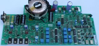
In the attached image you will find the component side from the PCB.
And a second question:
how many versions exists for AC motors (synchron motors) and how many versions exists for DC motors ?
Thanks for an advice.
Linn Lingo Power Supply, 1994 model breaking down
In the attached image you will find the component side from the PCB.
And a second question:
how many versions exists for AC motors (synchron motors) and how many versions exists for DC motors ?
Thanks for an advice.
Attachments
Last edited:
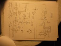
Schematic here
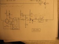
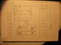
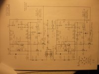
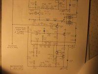
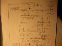
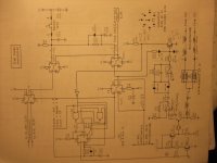
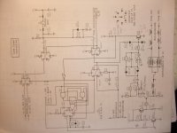
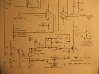
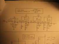
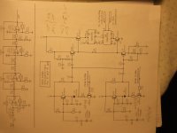
I found my self-made schematic of the version from previous posting by accident (go to attached images - it was in a place where I would normally never have put it).
At weekend I receive such a version for repair with follow unwanted effect:
The increased gain for the start-up phase of the plate returns again and again in the interval of 5 to 7 seconds.
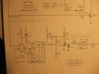
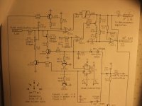
If there is a correct operating, Q10 - controlled by PIN5 (Q) of U4a - switches the resistor R14 (6K2) to the resistor R64 (150K), but only for any few seconds (start-up phase) until the target speed is reached.
Then the transistor Q10 turn off the resistor R14 and the gain factor is reduced and is only defined by R64 and an additional not showed NFB-Resistor (to maintain the speed).
The question is now, why the gain does not remain at the value for normal operating and goes back to the enhanced value for the start-up phase.
At PIN 14 of U2 (TL074) and collector Q14 so as at R123 (22R) and PIN2, U4 (74LS221 or 74HC221) is a square wave present (2V4ss) and a DC voltage of 2V2.
Maybe U4 must be replace (this is very difficult, because the PINs are bent over on the solder side).
The actually question is this:
How can I prove without desolder whether U4 is faulty or not?
Thank you for advices (go therefore to the first four attached images).
I found my self-made schematic of the version from previous posting by accident (go to attached images - it was in a place where I would normally never have put it).
At weekend I receive such a version for repair with follow unwanted effect:
The increased gain for the start-up phase of the plate returns again and again in the interval of 5 to 7 seconds.
If there is a correct operating, Q10 - controlled by PIN5 (Q) of U4a - switches the resistor R14 (6K2) to the resistor R64 (150K), but only for any few seconds (start-up phase) until the target speed is reached.
Then the transistor Q10 turn off the resistor R14 and the gain factor is reduced and is only defined by R64 and an additional not showed NFB-Resistor (to maintain the speed).
The question is now, why the gain does not remain at the value for normal operating and goes back to the enhanced value for the start-up phase.
At PIN 14 of U2 (TL074) and collector Q14 so as at R123 (22R) and PIN2, U4 (74LS221 or 74HC221) is a square wave present (2V4ss) and a DC voltage of 2V2.
Maybe U4 must be replace (this is very difficult, because the PINs are bent over on the solder side).
The actually question is this:
How can I prove without desolder whether U4 is faulty or not?
Thank you for advices (go therefore to the first four attached images).
Attachments
-
 DSCF6301.jpg808.1 KB · Views: 361
 -
 DSCF6307.jpg691.3 KB · Views: 311
 -
 DSCF6309.jpg790.8 KB · Views: 285
 -
 DSCF6311.jpg694 KB · Views: 303
 -
 DSCF6285.jpg766.6 KB · Views: 149
 -
 DSCF6287.jpg792.8 KB · Views: 161
 -
 DSCF6289.jpg760.2 KB · Views: 126
 -
 DSCF6291.jpg764 KB · Views: 159
 -
 DSCF6293.jpg757.1 KB · Views: 142
 -
 DSCF6294.jpg657.8 KB · Views: 181
Last edited:
- Status
- This old topic is closed. If you want to reopen this topic, contact a moderator using the "Report Post" button.
- Home
- Source & Line
- Analogue Source
- Linn Lingo schematic