The replace of U4 by a new device with socket did not fix the error.I found my self-made schematic of the version from previous posting by accident (go to attached images - it was in a place where I would normally never have put it).
At weekend I receive such a version for repair with follow unwanted effect:
The increased gain for the start-up phase of the plate returns again and again in the interval of 5 to 7 seconds.
If there is a correct operating, Q10 - controlled by PIN5 (Q) of U4a - switches the resistor R14 (6K2) to the resistor R64 (150K), but only for any few seconds (start-up phase) until the target speed is reached.
Then the transistor Q10 turn off the resistor R14 and the gain factor is reduced and is only defined by R64 and an additional not showed NFB-Resistor (to maintain the speed).
The question is now, why the gain does not remain at the value for normal operating and goes back to the enhanced value for the start-up phase.
At PIN 14 of U2 (TL074) and collector Q14 so as at R123 (22R) and PIN2, U4 (74LS221 or 74HC221) is a square wave present (2V4ss) and a DC voltage of 2V2.
Maybe U4 must be replace (this is very difficult, because the PINs are bent over on the solder side).
The actually question is this:
How can I prove without desolder whether U4 is faulty or not?
Thank you for advices (go therefore to the first four attached images).
During the further search for the cause of the error, I noticed the following drawing error when I was creating the circuit diagram at those days:
On U4B, pins 12, 11, 10 and 9 must be exchanged for pins 4, 3, 2 and 1.
With U4a, pins 4, 3, 2 and 1 must be exchanged for pins 12, 11, 10 and 9, i.e. exactly the opposite of U4B. This means that the schematic must be redrawn for correct understanding the theory of operation.
During further troubleshooting it turned out, that the voltage for correct operation must be 5V on C, Q22 and R22 and PIN9, U4. Because there is to measure only 2V2, the above desribed unwanted effect is present.
The question is now, how works the section arround Q3/13,R59, FET1, U3 and D7-10 (first image, post #40) and which voltage values are correct while start-up and normal operating phase.
Thank you for advices.
Last edited:
under
http://www.turntablepsu.com/images/Lingo Schematic.pdf
there is the same schematic in high resolution
http://www.turntablepsu.com/images/Lingo Schematic.pdf
there is the same schematic in high resolution
under
https://www.diyaudio.com/forums/ana...ontinously-stall-normal-mode.html#post6283928
is mentioned the same issue, if the term "stall-mode" means the same than "start"-mode.
https://www.diyaudio.com/forums/ana...ontinously-stall-normal-mode.html#post6283928
is mentioned the same issue, if the term "stall-mode" means the same than "start"-mode.
On further troubleshooting attempts I note, that after the removal of the transistor FET1 (J112/U1898) the device operates at first glance in the correct manner (i. e. the gain remains now in the low-gain mode after the start mode with high-gain).The replace of U4 by a new device with socket did not fix the error.
During the further search for the cause of the error, I noticed the following drawing error when I was creating the circuit diagram at those days:
On U4B, pins 12, 11, 10 and 9 must be exchanged for pins 4, 3, 2 and 1.
With U4a, pins 4, 3, 2 and 1 must be exchanged for pins 12, 11, 10 and 9, i.e. exactly the opposite of U4B. This means that the schematic must be redrawn for correct understanding the theory of operation.
During further troubleshooting it turned out, that the voltage for correct operation must be 5V on C, Q22 and R22 and PIN9, U4. Because there is to measure only 2V2, the above desribed unwanted effect is present.
The question is now, how works the section arround Q3/13,R59, FET1, U3 and D7-10 (first image, post #40) and which voltage values are correct while start-up and normal operating phase.
Thank you for advices.
I removed FET1 (J112) because it had a D-S connection despite the fact, that the gate voltage was -9V
The question now is as follow:
What are the tasks of the following parts:
U4 (PIN1-2-3-4-13-14-15), Q13, Q3 and FET1.
Last edited:
after replace the jFET by a new device from ON-semi the Lingo operates in the right manner, i. e. after brake by hand the motor pulley the motor voltage raises on the initial value (90VAC) for some seconds, to then return to the value for normal operating (50VDC). This wasn't the case without the jFET.
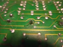
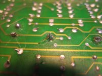
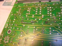
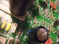
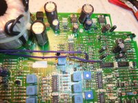
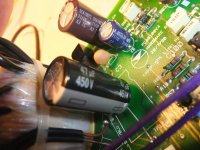
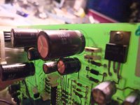
But the original issue occurs after a short time again and again the new jFET was defective (permanent conduction between drain and source, even at gate voltage from -9VDC). The reason therefore you will find in the attached images number one until five (the last four pictures shows the new electrolytic caps - all 63V and 450V versions).
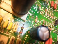
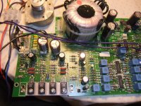
Before the electrolytic capacitors C20/21 were replaced, however, the interruption in the conductor track (between Choke 2 and C20 near by TP16B) that was visible on the first two images, was only a invisible hairline crack, which resulted in temporarily voltage peaks at the source of FET1 and R59 (4R7).
After the interruption of the conductor track has been eliminated and the FET1 replaced again, this motor control device from Linn is now working properly even after a long test phase.
Unfortunately such causes are always very hard to find.
But the original issue occurs after a short time again and again the new jFET was defective (permanent conduction between drain and source, even at gate voltage from -9VDC). The reason therefore you will find in the attached images number one until five (the last four pictures shows the new electrolytic caps - all 63V and 450V versions).
Before the electrolytic capacitors C20/21 were replaced, however, the interruption in the conductor track (between Choke 2 and C20 near by TP16B) that was visible on the first two images, was only a invisible hairline crack, which resulted in temporarily voltage peaks at the source of FET1 and R59 (4R7).
After the interruption of the conductor track has been eliminated and the FET1 replaced again, this motor control device from Linn is now working properly even after a long test phase.
Unfortunately such causes are always very hard to find.
Attachments
-
 DSCF6478.jpg985.9 KB · Views: 243
 -
 DSCF6479.jpg987.1 KB · Views: 278
 -
 DSCF6481.jpg991.9 KB · Views: 231
 -
 DSCF6482.jpg1,006.9 KB · Views: 246
 -
 DSCF6483.jpg992.2 KB · Views: 230
 -
 DSCF6487.jpg1 MB · Views: 332
 -
 DSCF6489.jpg1 MB · Views: 131
 -
 DSCF6493.jpg997.3 KB · Views: 111
 -
 DSCF6494.jpg999.4 KB · Views: 131
Last edited:
The Lingo is typical of when the boss of a company has a view of the engineering required and finds an engineer saying the right things. At this point no data exists.
A friend asked me to clone a Lingo. What I did was far simpler and I suspect better. The ramp voltage just a NE555 timer. In the process I took real life measurements. Not voltage but current distortion which is always high. The Lingo hides this if just voltage measurements due to low output impedance. Remember the DCR of the coils make the voltage measurements of very little use. Just because you can't see it doesn't mean it's gone.
I had a Lingo at the time and sold it. I took a Valhalla and found it to be a very nice design built down to a price. Some small improvements made and to my ears better than Lingo. I now use a Garrard 401. My Valhalla had more torque than the Lingo and still had reasonable vibraion. The Vallhalla can ramp if required. Phase shift by capacitor sellection is OK.
My goodness the Lingo is complex. I suspect to drive people like me away.
check out this threads:
Steuerung fur Plattenspielermotor/Synchronmotor - Phono - Restaurierung und Selbstbau - Analogue Audio Association
Linn Lingo vs. Dr. Fuß or Square-Wave vs. Sine Wave Oscillator for Motor Control
https://www.diyaudio.com/forums/ana...it-description-sine-wave-osc.html#post5995157
Steuerung fur Plattenspielermotor/Synchronmotor - Phono - Restaurierung und Selbstbau - Analogue Audio Association
Linn Lingo vs. Dr. Fuß or Square-Wave vs. Sine Wave Oscillator for Motor Control
https://www.diyaudio.com/forums/ana...it-description-sine-wave-osc.html#post5995157
Last edited:

This is inside a Crouzet 24 pole motor used in the Loricraft PRC. A Linn motor of the Lingo era looks very similar. This is a montage so there are fewer parts in the complete motor than seen here.
If a stepper motor calculator is fed with the Linn motor data I think I remember the resonant frequency is about 80 Hz. The two types of motor are similar. I would speculate 7.5 degree steppers came from synchronous motors.
I did a test with square, sine and triangle waves. A simple hand held vibration test and torque. Measuring the current waveforms showed almost identical results if output voltage carefully set! All were somewhere between square and triangle distortion. The magnetic circuit looks almost exactly like the current waveform. It should if you think about it. Voltage I would say is 90% of what we hear. Phase between coils needs to be 90 degrees +/- 5 degrees. Voltages within <5% if possible. Valhalla 90/80VAC was OK.
A Garrard 401/ Thorens TD124 show lower vibration for a given torque. The current wavefom also less distorted. Some imply these motors are less good because the compromises seem larger. Truth is they are better. The Linn motor is better than most of it's type. This seems mostly due to being built for task.
I tried a Crouzet motor in a Garrard 601. Great sound but rumble was about - 30 dB. Sometimes it was almost OK. LP12 circa - 72 dB 401 - 60 dB and 501 - 78 dB. - 60 dB is about where it needs to be and - 72 dB a bonus. The measuring method weighted to typical modern standards. 601 would be about - 72 dB. I don't think it was ever measured, the early 501 about - 69 dB.
What I must do if I want to adjust the motor voltage to the optimal value (for best results on S/N ratio) on the Linn LP12 (the original factory setting is 90 VAC while starting and 50VAC while normal operating) ?
And a second question:
which values were measured in the newer Lingo versions (pictures of those versions in post #73 under
Linn Lingo vs. Dr. Fuß or Square-Wave vs. Sine Wave Oscillator for Motor Control
- two PCB versions but three cabinet versions) ??
And a second question:
which values were measured in the newer Lingo versions (pictures of those versions in post #73 under
Linn Lingo vs. Dr. Fuß or Square-Wave vs. Sine Wave Oscillator for Motor Control
- two PCB versions but three cabinet versions) ??
Last edited:
Over the weekend I put a recently serviced Valhalla into an enclosure to hook up to my Thorens TD160 turntable. I've not put an isolation transformer in front of it as I was using an enclosure I had to hand. Too small for a transformer. That will be my next goal.
I added a mini 12VDC supply to power a relay board which switches the mains live. So I can at least power up/down the Valhalla when not using. The other addition I made was to add a daughter board on a header where the original switch was. This uses an RC delay into an XOR to turn the Thorens latching switch into a 10ms logic pulse to trigger the Valhalla. So the Thorens is stock, and I send 9V to the switch and Red/Blue/Black to the motor down a 5-way umbilical.
It all works as I'd hoped, but I'd like to increase the output voltage to avoid judder on startup. The original Thorens PSU (10K dropper and 0.15uF phase cap) measured 133AC + 111VAC with a phase angle of 104 degrees. So I'd like to set it for 100V on Red.
Playing around with the phase capacitor I've found the best voltage/phase I can get to be 90V + 85V, and a phase angle of 83 degrees with 0.3uF. (I've removed the Zener clipper circuit). Above 90V I start to see distortion on the second phase. Around 100V (Red) this become audible. I tried other phase cap values, but they lowered the voltage at which distortion set in and widened the phase angle.
My scope tells me the distortion is harmonics at 60Hz, 160Hz, 260Hz etc. So (finally!) my question to Valhalla experts: where is this coming from, and what can I do to nullify it?
Thanks!
Last edited:
The TD150 seems the same when I tried similar ideas. The Valhalla will work at 253 VAC if it helps. There is a preset near the 3.2768 MHz crystal that sets the output voltage. The waveform of the secondary phase is always more distorted and lower voltage. The 47 uF capacitors can be uprated to 220 uF. This gives about 10 dB ripple reduction and needs no changes.to the rectifier.I think you might get a reliable 105 VAC if doing this which should drive a TD160. The phase capacitor will most likely have to be changed. Linn used 220nF. The 47 uF is a DC blocking capacitor and is the third of that value. The other two. are PSU.
Thanks Nigel. I ordered the parts and opened up the Thorhalla this morning to fit them and noticed, idiot that I am, that I had the blue and black reversed where I terminated the umbilical on a tag strip in the deck.
When I swapped them back I was able to get the voltage I needed. It also explains why the deck was running forward with red direct, blue phased - the opposite of how the TD160 Super on-board PSU is wired. When I swapped them over voltage was available ... and the deck span backwards. All good!
I played with phase cap values and I'll note my findings here in case someone tries the same. I tried different phase caps and adjusted the output to get as close to a 90 degree phase angle as possible:
0.15uF 86+82V - juddering start
0.20uF 119+105V - works fine. I settled on this value
0.22uF 132+116V - which were the voltages I measured from the original resistor/capacitor PSU
So slightly lower voltages than as built, but closer to the rating of the fitted motor, and tenths of a degree away from a 90 degree angle. A multi turn trim pot would make it easier to nail that exactly, but I doubt a fraction of a degree is important.
P.S. Anyone need some fat 220uF/250V Illinois caps?")
When I swapped them back I was able to get the voltage I needed. It also explains why the deck was running forward with red direct, blue phased - the opposite of how the TD160 Super on-board PSU is wired. When I swapped them over voltage was available ... and the deck span backwards. All good!
I played with phase cap values and I'll note my findings here in case someone tries the same. I tried different phase caps and adjusted the output to get as close to a 90 degree phase angle as possible:
0.15uF 86+82V - juddering start
0.20uF 119+105V - works fine. I settled on this value
0.22uF 132+116V - which were the voltages I measured from the original resistor/capacitor PSU
So slightly lower voltages than as built, but closer to the rating of the fitted motor, and tenths of a degree away from a 90 degree angle. A multi turn trim pot would make it easier to nail that exactly, but I doubt a fraction of a degree is important.
P.S. Anyone need some fat 220uF/250V Illinois caps?
comparison by a listening test between Linn's LINGO and AXIS power supply - go to post 12 under
https://www.diyaudio.com/forums/ana...-description-sine-wave-osc-2.html#post6475049
https://www.diyaudio.com/forums/ana...-description-sine-wave-osc-2.html#post6475049
- Status
- This old topic is closed. If you want to reopen this topic, contact a moderator using the "Report Post" button.
- Home
- Source & Line
- Analogue Source
- Linn Lingo schematic