Hi Tom,
I included the 1 ohm resistors because the amplifiers are specc'd for a minimum load of 2 ohms. I'm only using a 12v power supply so I worked out that an extra 1ohm in series with the transformer should do the trick in limiting the startup current. I actually bought a few spare amplifiers just in case I guessed wrong
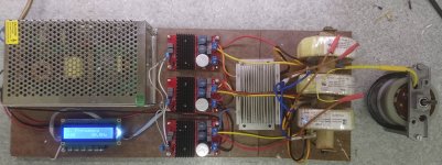
I've been running the setup in the picture for a few days almost non-stop. The amps run almost cold, the transformers are at about 45 degC, in fact its only the heatsink over the resistors that get at all hot, and that's easily fixed by the addition of a 12v computer fan reattached to the heatsink.
The motors (I have 2 different Papst motors) run almost completely silently, only a very slight 'woosh' of the air moved by the external rotor gives any indication they are moving.
Hi Ralph,
Nice to see a working proto.
I have a few questions:
1) Do you really need those 1 Ohm resistors.
An Amp that can supply 100Watt to 2 Ohm, can supply 14Amp rms or 20Amp peak and that with 3 Amps simultaneously! Most likely way beyond what your motor draws at start-up.
Your Power supply would also prevent that long before with 10Amp max .
2) What is the gain of the used amps, it is not in the ebay description.
Probably some 30dB?
3) The output voltage of the 3 phase generator is supposed to be variable from 1V to 5V rms.
Even 1V is probably too much with these Amps so you will probably need three simple 1:10 voltage dividers in front of the amps?
Hans
Last edited:
Hi Ralph,
Nice to see a working proto.
I have a few questions:
1) Do you really need those 1 Ohm resistors.
An Amp that can supply 100Watt to 2 Ohm, can supply 14Amp rms or 20Amp peak and that with 3 Amps simultaneously! Most likely way beyond what your motor draws at start-up.
Your Power supply would also prevent that long before with 10Amp max .
2) What is the gain of the used amps, it is not in the ebay description.
Probably some 30dB?
3) The output voltage of the 3 phase generator is supposed to be variable from 1V to 5V rms.
Even 1V is probably too much with these Amps so you will probably need three simple 1:10 voltage dividers in front of the amps?
Hans
Hi Hans,
I tried leaving out the resistors and got no output, I suspect the Amplifiers see something too close to a short circuit across the 12v side of the transformer and won't start. Reinstalling the resistors all is well.
I do use a resistive divider on the input to the Amps, I also use a 0.47 uF capacitor across each amp input to reduce/eliminate any 'hash' from the generator.
The gain is, as you suspected around 30dB.
The next stage is to machine a suitable pulley for the motor, then swap out the E50 motor on my TD124 for the Papst, and see if I can detect any difference.
At that point I shall find a suitable case for the 3 phase generator and box it all up.
")
Hi Hans,
I tried leaving out the resistors and got no output, I suspect the Amplifiers see something too close to a short circuit across the 12v side of the transformer and won't start. Reinstalling the resistors all is well.
That may be the reason why Pyramid had start-up problems with several of his attempts.
Good to know.
Hans
You are talking about 3 phase one (first link) and use it for only 1 phase with 90 Deg shift, and to add two step-up transfos to convert
from 6v to 115v?
Sent from my iPhone using Tapatalk
It is a bit difficult to understand your question. But from a 3 phase generator, you can use 2.
Add two amps and two trafo's and you can drive your two phase motor without the capacitor.
That's the basic idea.
Hans
It is a bit difficult to understand your question. But from a 3 phase generator, you can use 2.
Add two amps and two trafo's and you can drive your two phase motor without the capacitor.
That's the basic idea.
Hans
I'm sorry for confusion. I'm new to the subject and trying to understand the general concept. What are mentioned transformers for? I thought you are talking about PSUs tranys. Is it some type of output tranys? Can you please edit my sketch

I'm sorry for confusion. I'm new to the subject and trying to understand the general concept. What are mentioned transformers for? I thought you are talking about PSUs tranys. Is it some type of output tranys? Can you please edit my sketch?
Unless you have amps able to supply 115V rms, the trafo's are meant to transform ca. 15Vrms Amp output to 60Hz/115V or 50hz/230v, depending on where you live, see also posting #1.
Hans
OK got the gen/splitter and the 100 watt mono amps coming. So I need a power supply and some step up transformers. So if I go at this backwards let say I want to build for a 30 watt motor. How many amp power supply would get the job done. The gen/split only needs 50 ma. The amp can take 12-24 DC. I have a computer supply that outputs 15 volts at 5 amps. And its free!!!
The other variable is the gen/splitter can output 1-5 volts. So would you go to 12 or 24 volts to the step up to get to 120volts to the motor. Need to know this so I get the right step ups. A transformer guy seem to think 25va transformer could handle the 30 watt motor.
I am also guessing that by adjusting the output signal on the gen/split you drop the voltage to the motor if needed.
Thanks for all the help so far everyone.
It is going to be fun to get rid of the cap on the hurst motors and try 3 phase on a bldc motor.
Tom
I corrected diagram. BTW, it is regular power transformer like 120v or 115v input to 15v or whatever needed for output, but reversed. So, 15v in and 120v out.
Sent from my iPhone using Tapatalk
Excuse my ignorance, but do two 10W resistors have enough margin if the motor is 15W when running steady?
BTW, i got a kick out of your "Sin generator", a generator of Sin
 as the input (instead of sine).
 Excuse my ignorance, but do two 10W resistors have enough margin if the motor is 15W when running steady?
I'm using 10W resistors for my setup, they're there to stop the amplifier shutting down when it sees an effective short circuit from the transformer at startup. In my case I'm losing about 20% of the power across the resistors and they do get quite warm, even when bolted to the bottom of the heatsink.
Remember though that I'm driving a 3 phase 30W motor
Attachments
I'm using 10W resistors for my setup, they're there to stop the amplifier shutting down when it sees an effective short circuit from the transformer at startup. In my case I'm losing about 20% of the power across the resistors and they do get quite warm, even when bolted to the bottom of the heatsink.
Remember though that I'm driving a 3 phase 30W motor
30Watt motor means 10Watt per phase.
With 15V coming from the Amp's, that results in 0.7Amp.
Power per resistor is I^2 x R = 0.5 x 1 = 0.5 watt.
So 10 Watt resistors are more than O.K.
Hans
Hey Ralph
How did you settle in with a 120 va power supply? Did you measure the current on the amps you used or just took a stab and make it big. I am going to use the ones you posted in the thread and want to use the 12v 5amp one I have or order one. It seems no one wants to take a stab on what those 100 watt mono amp will consume. I will probably try a bldc motor 3 phase at 30 watts so that looks Iike what you did.
Thanks Tom
Hi Tom,
I didn't choose the 12v supply especially, its just one I had lying around. As far as the motor power requirements are concerned the 30W was a bit of a WAG. The Papst motors are notoriously inefficient; I've dug out my clamp meter and here are the readings of my current setup
Amp output voltage 6.5V per phase
Amp output current 2.8A " "
Remember I am using 12+12 ~ 230V 30 VA transformers (12v primaries in parallel) to generate a 120V supply for the motor
This means that each amp power output is around 20W (ignoring p.f. correction)
A 60VA PSU is running too close to the limit; I would use at least a 100VA unit.
I'm going to try using a 24V supply, and run with the 12V primaries in series, this may allow me to get rid of the ballast resistors, though I will obviously have to adjust the input attenuators for the amps.
I'll let you know how I get on
- Status
- This old topic is closed. If you want to reopen this topic, contact a moderator using the "Report Post" button.
- Home
- Source & Line
- Analogue Source
- Optimally driving a (VPI) synchronous turntable motor