Konnichiwa,
Good idea.
Not really. Franks circuit as originally drawn had a number of differences to yours which would have made the resulting noise on the +B sufficiently low. However it is a lot of effort and added Valves with very little benefit. Hence my suggestion of a very basic supply.
If you want to regulate I would recommend STRONGLY using current sourced shunt regulators, one per Stage and you will find a basic TL431 & Cascode FET plus LM317 & Cascode FET current source infinitly superior to even the best Valve Series regulators.
However, I feel that such extreme effort is not required and is better reserverd for more extreme Phono Stage designs. After all, despite a lot of fancy components the actual design is quite basic and cheap to realise.
Moreover, regulators are in most cases based around looped feedback amplifiers, which by definition implies inherent instability, so layout and implementation can be critical. If you don't get it right you might spend days or weeks chasing humps and pumping that are reallyvhf oscillations of the regulated PSU which you cannot see on the usual 20MHz 'scopes.... The "sound" of regulatorsmis another topic again....
Well, normal resistor series do not contain a 50K Value. So if the nominal is 50K then NPV (Nearest Preferred Value) is 51k... ;-)
Highly recommended. My current phonostage is S&B TX-103 into Pentode E810F into S&B EQ-600 into D3a triode connected. This drives a S&B TX-102 passive linestage. Sounds great, though cost is substantial.
Hmmm. This from my files....
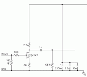
l'Audiophile MC Pre-Pre
<pre>
24 Volts regulated or battery buffered supply
|
|
4k7
|
|---------0.47uF-----out------------>
| |
(drain) |
---in---------(gate)JFET 100k
| (source) |
100R | |
| 47R |
| | |
-ground--------------------------------------------------
</pre>
The basic topology is that of the second step-up amplifier by "Maison de L'Audiophile" of Paris/France.
The first 100R is the cartridge load, which must be adapted for the cartridge you use. Using a paralleled 1nF cap also makes the circuit immune against RF noise. The 47R resistor in the source is not necessary, if the JFET has an IDSS(on) of 2mAmps or less.
As the signals are very sensitive, the voltage must be very clean, a 100,000 uF electrolytic cap for blocking power supply noise, computer grade favourably, is advisable. (note - we used 2 X 2,200uF Elna Starget and a 1k Decoupling resistor.)
Suitable JFETS are 2SK170, 2SK240 (double JFET), 2SK97 (double JFET), sorry only these japanese types are suitable, the European BC264 and BF254 and so on do not work here (I tried !). All resistors must be big metall resistors, e.g. Beyschlag 1Watt, or tantalum resistors. No carbon resistors allowed here, tubes addicts.
The output cap is preferably polystyrene or polypropylene or paper-in-oil, as you like it, as they are different in sonic balance. If the load is lower than 100K you need to increase the capacitor proportionatly.
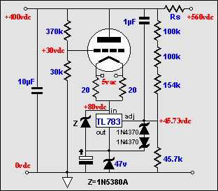
If you use a passive RCRCRCRCRC filter chain with 1k/100uF cells you will have 30mA X 5k voltage drop in the RC filter chain, namely 150V. Add to this the 250V +B and you need 400V. If you use a 6X4 or EZ80 rectifier valve and a 10uF reservoir capacitor you will be needing a 320V-0-320V Transformer with a DC rating > 30mA or an AC rating of at least 50mA or thereabouts.
I have attached the suggested PSU schematic for a simple and cheap PSU that is dead quiet, uses a valve rectifier and is entierly passive and hence should be pretty safe and reliable to assemble. The Electrolytic Capacitors can be quite inexpensive types but should be bypassed, the 10uF reservoir capacitor however should be a decent MKP type, to shortcircuit as much HF noise as possible.
Sayonara
GAK said:I think I'll build Kuei's circuit as it is and then I'll try different PSUs. Then I'll have my own opinion.
Good idea.
GAK said:It's very funny that everyone has sth different to say.
Not really. Franks circuit as originally drawn had a number of differences to yours which would have made the resulting noise on the +B sufficiently low. However it is a lot of effort and added Valves with very little benefit. Hence my suggestion of a very basic supply.
If you want to regulate I would recommend STRONGLY using current sourced shunt regulators, one per Stage and you will find a basic TL431 & Cascode FET plus LM317 & Cascode FET current source infinitly superior to even the best Valve Series regulators.
However, I feel that such extreme effort is not required and is better reserverd for more extreme Phono Stage designs. After all, despite a lot of fancy components the actual design is quite basic and cheap to realise.
Moreover, regulators are in most cases based around looped feedback amplifiers, which by definition implies inherent instability, so layout and implementation can be critical. If you don't get it right you might spend days or weeks chasing humps and pumping that are reallyvhf oscillations of the regulated PSU which you cannot see on the usual 20MHz 'scopes.... The "sound" of regulatorsmis another topic again....
GAK said:If the nominal is 50K why not to use a 50K resistor?
Well, normal resistor series do not contain a 50K Value. So if the nominal is 50K then NPV (Nearest Preferred Value) is 51k... ;-)
GAK said:The S&B are too expansive but I think they're worth the money. In the future I'll try them.Especially the 600R riaa eq.
Highly recommended. My current phonostage is S&B TX-103 into Pentode E810F into S&B EQ-600 into D3a triode connected. This drives a S&B TX-102 passive linestage. Sounds great, though cost is substantial.
GAK said:Can you suggest me sth not so expensive for MC step up?
Hmmm. This from my files....
l'Audiophile MC Pre-Pre
<pre>
24 Volts regulated or battery buffered supply
|
|
4k7
|
|---------0.47uF-----out------------>
| |
(drain) |
---in---------(gate)JFET 100k
| (source) |
100R | |
| 47R |
| | |
-ground--------------------------------------------------
</pre>
The basic topology is that of the second step-up amplifier by "Maison de L'Audiophile" of Paris/France.
The first 100R is the cartridge load, which must be adapted for the cartridge you use. Using a paralleled 1nF cap also makes the circuit immune against RF noise. The 47R resistor in the source is not necessary, if the JFET has an IDSS(on) of 2mAmps or less.
As the signals are very sensitive, the voltage must be very clean, a 100,000 uF electrolytic cap for blocking power supply noise, computer grade favourably, is advisable. (note - we used 2 X 2,200uF Elna Starget and a 1k Decoupling resistor.)
Suitable JFETS are 2SK170, 2SK240 (double JFET), 2SK97 (double JFET), sorry only these japanese types are suitable, the European BC264 and BF254 and so on do not work here (I tried !). All resistors must be big metall resistors, e.g. Beyschlag 1Watt, or tantalum resistors. No carbon resistors allowed here, tubes addicts.
The output cap is preferably polystyrene or polypropylene or paper-in-oil, as you like it, as they are different in sonic balance. If the load is lower than 100K you need to increase the capacitor proportionatly.
GAK said:Can you exlain me why the raw DC after rectification and cap must be around 400V?Isn't it too much?
If you use a passive RCRCRCRCRC filter chain with 1k/100uF cells you will have 30mA X 5k voltage drop in the RC filter chain, namely 150V. Add to this the 250V +B and you need 400V. If you use a 6X4 or EZ80 rectifier valve and a 10uF reservoir capacitor you will be needing a 320V-0-320V Transformer with a DC rating > 30mA or an AC rating of at least 50mA or thereabouts.
I have attached the suggested PSU schematic for a simple and cheap PSU that is dead quiet, uses a valve rectifier and is entierly passive and hence should be pretty safe and reliable to assemble. The Electrolytic Capacitors can be quite inexpensive types but should be bypassed, the 10uF reservoir capacitor however should be a decent MKP type, to shortcircuit as much HF noise as possible.
Sayonara
Attachments
Konnichiwa,
Seems this board ignores any sensible old syntax to force the text to be handled as Text, okay, attached a gif of the circuit....
Can be supplied from 12V DC but not 6V....
I would recommend making a solidly regulated and low noise 15V Heater supply and tapping of via resistors the 12V for the ECC83 and the 6V for the ECC88. Note the statement of 6V, not 6.3V, underheating Valves slightly lengthens life and sound better. Then tap of the 15V via a RCRCRC circuit using 100R/1,000uF...2,200uF per filter cell.
Sayonara
Kuei Yang Wang said:
l'Audiophile MC Pre-Pre
<pre>
24 Volts regulated or battery buffered supply
|
|
4k7
|
|---------0.47uF-----out------------>
| |
(drain) |
---in---------(gate)JFET 100k
| (source) |
100R | |
| 47R |
| | |
-ground--------------------------------------------------
</pre>
Seems this board ignores any sensible old syntax to force the text to be handled as Text, okay, attached a gif of the circuit....
Can be supplied from 12V DC but not 6V....
I would recommend making a solidly regulated and low noise 15V Heater supply and tapping of via resistors the 12V for the ECC83 and the 6V for the ECC88. Note the statement of 6V, not 6.3V, underheating Valves slightly lengthens life and sound better. Then tap of the 15V via a RCRCRC circuit using 100R/1,000uF...2,200uF per filter cell.
Sayonara
Attachments
Hi,
It seems you're understating this...
From the Philips library in Eindhoven: lowering the heater voltage from 6.3V to 6.1V will double the life expectancy of the valve without any loss of performance.
Re: MC stage, as an alternative you can build a valved one using a pair of ECC88s per channel run from a 24VDC supply and CCS loaded.
Cheers,")
Note the statement of 6V, not 6.3V, underheating Valves slightly lengthens life and sound better.
It seems you're understating this...
From the Philips library in Eindhoven: lowering the heater voltage from 6.3V to 6.1V will double the life expectancy of the valve without any loss of performance.
Re: MC stage, as an alternative you can build a valved one using a pair of ECC88s per channel run from a 24VDC supply and CCS loaded.
Cheers,
I use both a FET based and ECC88 MC step-ups. All with tantalum resistors and MIT RTX output caps and NiMH batteries and always thought both sounded great in comparison to transformers.
Recently, i have been using a cheap Lundahl which sounded ok with my Kontra b. After about a 100hr of break in its sound changed dramatically, up to the stage of being clearly preferable to the active step-ups.
Recently, i have been using a cheap Lundahl which sounded ok with my Kontra b. After about a 100hr of break in its sound changed dramatically, up to the stage of being clearly preferable to the active step-ups.
Konnichiwa,
The levels with MC cartridges are so low that the transformer will NEVER burn in. There are material issues around the setteling of the magnetic core material and the wire.
Simply follow the instructions I send to Arthur Salvatore, quoted here from his site:
http://www.high-endaudio.com/RC-Step-ups.html
=============================
Break-In Instructions from Thorsten Loesch
This worked very well for me, so I recommend it highly. This is what Loesch wrote, with a little editing:
"(The TX-103)... will require a substantial period of "forced burn in" to give it's best, simply because the magnetic core is huge and will not see much magnetisation with normal MC signals. Please consider connecting a CD-Player to the secondary (Output) of the TX-103 and then terminate the input with a low resistance resistor (quality uncritical), I'd say 27 Ohm when connected for 14db gain, 6.8 Ohm when connected for 20db gain and 2.2 Ohm when connected for 26db gain. Leave with a highly dynamic, wide bandwidth signal CD to play for a week or two. I would use music, but I'd expect pink noise to work well too."
Personal Note- While on a week's trip, I connected the signal (a tuner on a 24 hour "grundge" station) to the primary (Input) instead, and had great results. The rest of the circuit followed Loesch's instructions.
========================================
Sayonara
analog_sa said:Recently, i have been using a cheap Lundahl which sounded ok with my Kontra b. After about a 100hr of break in its sound changed dramatically, up to the stage of being clearly preferable to the active step-ups.
The levels with MC cartridges are so low that the transformer will NEVER burn in. There are material issues around the setteling of the magnetic core material and the wire.
Simply follow the instructions I send to Arthur Salvatore, quoted here from his site:
http://www.high-endaudio.com/RC-Step-ups.html
=============================
Break-In Instructions from Thorsten Loesch
This worked very well for me, so I recommend it highly. This is what Loesch wrote, with a little editing:
"(The TX-103)... will require a substantial period of "forced burn in" to give it's best, simply because the magnetic core is huge and will not see much magnetisation with normal MC signals. Please consider connecting a CD-Player to the secondary (Output) of the TX-103 and then terminate the input with a low resistance resistor (quality uncritical), I'd say 27 Ohm when connected for 14db gain, 6.8 Ohm when connected for 20db gain and 2.2 Ohm when connected for 26db gain. Leave with a highly dynamic, wide bandwidth signal CD to play for a week or two. I would use music, but I'd expect pink noise to work well too."
Personal Note- While on a week's trip, I connected the signal (a tuner on a 24 hour "grundge" station) to the primary (Input) instead, and had great results. The rest of the circuit followed Loesch's instructions.
========================================
Sayonara
Break-In Instructions from Thorsten Loesch
Ingenious as usually
I just hooked a scaled down tuner ouput for a couple of weeks to the primary (normally loaded secondary), watched the current in the primary to not outrageously exceed what a healthy MC would supply as i am fearful of 'overburn' and occassionally gave a listen as i wouldn't want my transformers to be fed silly SA garbage music or too many ads
It may or not be a real break in but the sound transformed at around 30 hrs.
cheers
Konnichiwa,
Next time don't scale it....
I recommend the full 9 inch from a CD Player (0dbfs pink noise) for the SECONDARY of a MC stepup heavily loaded and about as much level as you can get (something like a 50W RMS Amp!!!!) for something like a 102.... The key is the core material. I hear transformers get better over YEARS. I got fed up with waiting.... Same thing for speaker drivers.... On BG Cap's it seems even with "forced burn in" my patience is insufficient though...
Yes, JB from S&B was EXTREMELY sceptical. He heard the differences having 102's in his home system on the sky digibox (digital satellite TV) during footballing football games and was heard to mutter "I'd never"....
Transformers beat ANY other audio component I know, excepting certain speaker driver on burn in. Next to them most resistors and capacitors barely change and valves a little.
Must be all that magnetic core material, as holding a srong magnet next to transformer pretty reliably reverses the "burn in" process....
Sayonara
analog_sa said:I just hooked a scaled down tuner ouput
Next time don't scale it....
I recommend the full 9 inch from a CD Player (0dbfs pink noise) for the SECONDARY of a MC stepup heavily loaded and about as much level as you can get (something like a 50W RMS Amp!!!!) for something like a 102.... The key is the core material. I hear transformers get better over YEARS. I got fed up with waiting.... Same thing for speaker drivers.... On BG Cap's it seems even with "forced burn in" my patience is insufficient though...
analog_sa said:It may or not be a real break in but the sound transformed at around 30 hrs.
Yes, JB from S&B was EXTREMELY sceptical. He heard the differences having 102's in his home system on the sky digibox (digital satellite TV) during footballing football games and was heard to mutter "I'd never"....
Transformers beat ANY other audio component I know, excepting certain speaker driver on burn in. Next to them most resistors and capacitors barely change and valves a little.
Must be all that magnetic core material, as holding a srong magnet next to transformer pretty reliably reverses the "burn in" process....
Sayonara
First of all "thanks for the help"
Some more questions
Kuei
- What kind of resistors to use at the RC chain?
- 100uF: MKP or electrolytic - bypassed?
- What if change the 1K resistors with chokes??
analog_sa
- Are you reffering to LL9206?Have you tried an other one that Lundhal offers with internal screening?I think LL1681.
Some more questions
Kuei
- What kind of resistors to use at the RC chain?
- 100uF: MKP or electrolytic - bypassed?
- What if change the 1K resistors with chokes??
analog_sa
- Are you reffering to LL9206?Have you tried an other one that Lundhal offers with internal screening?I think LL1681.
Konnichiwa,
These will pretty 8uncritical, even "white coffin" Units should be fine, 2W Metal Films will work okay as well.
The parts quality is really a fundamental question. If you want an "all out" design, I can suggest something considerably different, which will be a LOT better.
The PSU and signal circuit discussed are aimed at providing a reasonable performance, to be easy to make work and to be inexpensive. There is no harm in using MKP's but I would restrict myself to the Input Cap's and the final Capacitors in the Phonochassis, if good performance is desired, without going overboard.
Sure, can be done. And you can change the Signal Valves and use a LCR RIAA Unit, by that time you have about the Phonostage I am listening to at the moment....
If you want something that is a little past the design discussed here, look here:
http://www.jogis-roehrenbude.de/Leserbriefe/TH-Loesch-Line/TOCCATA_RIAA.htm
This Phonostage uses only MKP Capacitors in the PSU, has a heavily overbuild PSU, uses rare and expensive Valves (now E810F in the Input and D3a in the output) as well as expensive Stepup transformers and an LCR RIAA. Those who have build copies have been very taken with the performance, it IS worth all the money pumped into it.
Sayonara
GAK said:What kind of resistors to use at the RC chain?
These will pretty 8uncritical, even "white coffin" Units should be fine, 2W Metal Films will work okay as well.
GAK said:100uF: MKP or electrolytic - bypassed?
The parts quality is really a fundamental question. If you want an "all out" design, I can suggest something considerably different, which will be a LOT better.
The PSU and signal circuit discussed are aimed at providing a reasonable performance, to be easy to make work and to be inexpensive. There is no harm in using MKP's but I would restrict myself to the Input Cap's and the final Capacitors in the Phonochassis, if good performance is desired, without going overboard.
GAK said:What if change the 1K resistors with chokes??
Sure, can be done. And you can change the Signal Valves and use a LCR RIAA Unit, by that time you have about the Phonostage I am listening to at the moment....
If you want something that is a little past the design discussed here, look here:
http://www.jogis-roehrenbude.de/Leserbriefe/TH-Loesch-Line/TOCCATA_RIAA.htm
This Phonostage uses only MKP Capacitors in the PSU, has a heavily overbuild PSU, uses rare and expensive Valves (now E810F in the Input and D3a in the output) as well as expensive Stepup transformers and an LCR RIAA. Those who have build copies have been very taken with the performance, it IS worth all the money pumped into it.
Sayonara
Hi all,
This turns to be a really nice thread....
Kuei,
Could you please give more details ( or references ) on that ?
The Lm317 based regulator, you suggested at the beggining of the thread is like the schem I posted (2nd page) or something different ?
This turns to be a really nice thread....
Kuei,
If you want to regulate I would recommend STRONGLY using current sourced shunt regulators, one per Stage and you will find a basic TL431 & Cascode FET plus LM317 & Cascode FET current source infinitly superior to even the best Valve Series regulators.
Could you please give more details ( or references ) on that ?
The Lm317 based regulator, you suggested at the beggining of the thread is like the schem I posted (2nd page) or something different ?
Konnichwa,
I hope this (from Tubecad) gives you the idea.
No, it is basically like yours, except FEt as cascode element and slightly different ways doing the rest....
Sayonara
Marinos said:
Could you please give more details ( or references ) on that ?
I hope this (from Tubecad) gives you the idea.
Marinos said:
The Lm317 based regulator, you suggested at the beggining of the thread is like the schem I posted (2nd page) or something different ?
No, it is basically like yours, except FEt as cascode element and slightly different ways doing the rest....
Sayonara
Hi
Kuei
Thanks for the detailed explanation.I didn't expect total current of 30mA.
Can you tell me how much current needs each tube?
I can't understand anything in this site.But I visited your site ( very nice system! ) and I saw your phono.In the future I'll try it.(The schem isn't clearly enough to understand.)
And more expensive.Sorry if I confused you with so many questions without estimate the final price of my project.
I'm not planning to go overboard right now so I'll build the phono we are disgussing over here with Shindo style PSU.
But I have some more "newbie"questions.
- You reccomend to bypass the electrolytic caps.What is better,to bypass each separetely with 1uF MKP or only one bypass at the end of the chain?
- I found 2u2 KP-SN at 100V.How much is the anode voltage of ECC88?Bigger than 100V I found 1u8 / 250V.
- Will one choke at the front of the chain do anything better?I have two 10H/100mA 74R and one 20H/200mA 48R.Or to live the PSU as it is?
Kuei
If you use a passive RCRCRCRCRC filter chain with 1k/100uF cells you will have 30mA X 5k voltage drop in the RC filter chain, namely 150V. Add to this the 250V +B and you need 400V. If you use a 6X4 or EZ80 rectifier valve and a 10uF reservoir capacitor you will be needing a 320V-0-320V Transformer with a DC rating > 30mA or an AC rating of at least 50mA or thereabouts.
Thanks for the detailed explanation.I didn't expect total current of 30mA.
Can you tell me how much current needs each tube?
http://www.jogis-roehrenbude.de/Les...OCCATA_RIAA.htm
I can't understand anything in this site.But I visited your site ( very nice system! ) and I saw your phono.In the future I'll try it.(The schem isn't clearly enough to understand.)
The parts quality is really a fundamental question. If you want an "all out" design, I can suggest something considerably different, which will be a LOT better.
And more expensive.Sorry if I confused you with so many questions without estimate the final price of my project.
I'm not planning to go overboard right now so I'll build the phono we are disgussing over here with Shindo style PSU.
But I have some more "newbie"questions.
- You reccomend to bypass the electrolytic caps.What is better,to bypass each separetely with 1uF MKP or only one bypass at the end of the chain?
- I found 2u2 KP-SN at 100V.How much is the anode voltage of ECC88?Bigger than 100V I found 1u8 / 250V.
- Will one choke at the front of the chain do anything better?I have two 10H/100mA 74R and one 20H/200mA 48R.Or to live the PSU as it is?
[Konnichiwa,
The ECC83 will draw around 1mA, the ECC88 will be (depending upon the specific valve used) around 14mA. With a "bogey" ECC88 & ECC83 each channel will draw around 15mA (=/-20%).
It's german. Try putting the fish in your ear (babel.altavista.com)
Bypass all. The problem is - most HV electrolytic cap's have a rather high ESR and ESL (Equvalent Series R / L) which stops them behaving as capacitors at higher frequencies. So without bypassing any high frequency noise just "rides through" most of the filter chain.
1u8 will be fine. I'd stick to 250V rating.
Most likely it will make things worse. LC circuits imply resonances, these can be difficult to handle. The noise is rejected very much by the RC chain, adding more filtering will not improve anything. If you build a fully LC filtered chain you can reduce the number of secytions and you need less raw HT, but you are now dealing with highly resonant circuits having their resonances in the same region as record warp etc. I'd recommend sticking to RC for the time being, less to go wrong.
Sayonara
GAK said:Can you tell me how much current needs each tube?
The ECC83 will draw around 1mA, the ECC88 will be (depending upon the specific valve used) around 14mA. With a "bogey" ECC88 & ECC83 each channel will draw around 15mA (=/-20%).
GAK said:I can't understand anything in this site.
It's german. Try putting the fish in your ear (babel.altavista.com)
GAK said:- You reccomend to bypass the electrolytic caps.What is better,to bypass each separetely with 1uF MKP or only one bypass at the end of the chain?
Bypass all. The problem is - most HV electrolytic cap's have a rather high ESR and ESL (Equvalent Series R / L) which stops them behaving as capacitors at higher frequencies. So without bypassing any high frequency noise just "rides through" most of the filter chain.
GAK said:I found 2u2 KP-SN at 100V.How much is the anode voltage of ECC88?Bigger than 100V I found 1u8 / 250V.
1u8 will be fine. I'd stick to 250V rating.
GAK said:Will one choke at the front of the chain do anything better?
Most likely it will make things worse. LC circuits imply resonances, these can be difficult to handle. The noise is rejected very much by the RC chain, adding more filtering will not improve anything. If you build a fully LC filtered chain you can reduce the number of secytions and you need less raw HT, but you are now dealing with highly resonant circuits having their resonances in the same region as record warp etc. I'd recommend sticking to RC for the time being, less to go wrong.
Sayonara
Hi
I'm going to order all the parts.Hope everything will go fine.
My only problem is that I don't think I'll find PTFE sockets.I'll use ceramic for now.
Thank you all for your help especially Kuei.
If I have a problem you will see a new thread.
If there's not any problem you will see a pic at the foto gallery.
Kuei : If you don't mind I'll mail you when I'll finish it to tell you my comments.
Hi,
I still have some.
They're skirted, noval and for chassis mounting.
Let me know how many you'd need by e-mail if you'd like some.
Cheers,
My only problem is that I don't think I'll find PTFE sockets.
I still have some.
They're skirted, noval and for chassis mounting.
Let me know how many you'd need by e-mail if you'd like some.
Cheers,
Konnichiwa,
Look around among Surplus shops (on and off-line), most have plenty of noval PTFE/Silverplated Brass contact Sockets and tend to sell them for the same as ceramic ones.
Sure, I'd appreciate it.
Sayonara
GAK said:My only problem is that I don't think I'll find PTFE sockets.I'll use ceramic for now.
Look around among Surplus shops (on and off-line), most have plenty of noval PTFE/Silverplated Brass contact Sockets and tend to sell them for the same as ceramic ones.
GAK said:Kuei : If you don't mind I'll mail you when I'll finish it to tell you my comments.
Sure, I'd appreciate it.
Sayonara
What can I say,
TL has done it again. The phono he suggested sounds wonderful.
It's the best sounding phono I have constructed and I have costructed a lot.
I consider myself as a "constructor type" since I do'nt have the background to comment / analyze / criticize a design. So here are some comments for people like me.
1. Build this phono as a drug to the "Best Part" syndrom. This time I resisted to these tiny evils coming at night telling me "...I'm the best resistor in world. Buy me. Without me everything sounds awful..... ". I used what I had ( electrolytic capacitors, metal film resistors, MKP RIAA capacitors....) and the result proves me that it's the design that matters.
2. Watch out the 12K anode load of the ECC88. Last night at power up I saw smokes... Then I realized that I need at least a 5 watter at this position.
3. I've got zero noise from this phono...
GK do yourself an early easter present and build this phono.
Keui thanks...
Konnichiwa,
A basically poor design will never sound really good, no matter how many fancy componets you throw at it. Sadly, many "technically correct" designs also fail to work in reality (shame really).
However, depite sounding nice with "generic" parts, do consider upgrading the RIAA Cap's and the interstage coupling Cap. Old Stock Silver Mica > 250V Rating (buy a few extra and test for leakage at high voltage!!! - If neccesary try to "burn out" any leakage) tend to be still best, sonically and in 1nF/10nF are not that hard to find.
Resistors, I'm pragmatic, the best is good enough.... ;-)
Yes, I'd suggest an Industrial TO220 encased type with heatsink. The industrial Meggit / Caddock / Vishay-Sfernice TO220 Power resistors do not give up much in sonics to the expensive audiophile Caddocks (though these are another series). All other resistors are fairly uncritical in terms of dissipation.
In the context of my personal sonics I'd use a Rohpoint Wirewound as Anode resistor for the ECC83 and selected (after a while "baking" at 60 - 70 centigrade) Carbon Composite Resistors in all shunt positions, plus good metal films in series positions.
Output Coupling Cap to taste, my recommendation as said would be KP-SN Types nearest value to 2.2uF but no doubt Copperfoil & Teflon Excotica would be great too, if you have them around....
Well, as said, this Phono is very much a minimalist and basic, entry level design, there is bigger and better out there, but as a starting point it should do nicely.
Sayonara
Marinos said:TL has done it again. The phono he suggested sounds wonderful.
Marinos said:the result proves me that it's the design that matters.
A basically poor design will never sound really good, no matter how many fancy componets you throw at it. Sadly, many "technically correct" designs also fail to work in reality (shame really).
However, depite sounding nice with "generic" parts, do consider upgrading the RIAA Cap's and the interstage coupling Cap. Old Stock Silver Mica > 250V Rating (buy a few extra and test for leakage at high voltage!!! - If neccesary try to "burn out" any leakage) tend to be still best, sonically and in 1nF/10nF are not that hard to find.
Resistors, I'm pragmatic, the best is good enough.... ;-)
Marinos said:2. Watch out the 12K anode load of the ECC88. Last night at power up I saw smokes... Then I realized that I need at least a 5 watter at this position.
Yes, I'd suggest an Industrial TO220 encased type with heatsink. The industrial Meggit / Caddock / Vishay-Sfernice TO220 Power resistors do not give up much in sonics to the expensive audiophile Caddocks (though these are another series). All other resistors are fairly uncritical in terms of dissipation.
In the context of my personal sonics I'd use a Rohpoint Wirewound as Anode resistor for the ECC83 and selected (after a while "baking" at 60 - 70 centigrade) Carbon Composite Resistors in all shunt positions, plus good metal films in series positions.
Output Coupling Cap to taste, my recommendation as said would be KP-SN Types nearest value to 2.2uF but no doubt Copperfoil & Teflon Excotica would be great too, if you have them around....
Well, as said, this Phono is very much a minimalist and basic, entry level design, there is bigger and better out there, but as a starting point it should do nicely.
Sayonara
Hi Kuei,
m'I right to prefer molded (axial) instead of dipped (radial) micas?
All molded that I bought in the past were not magnetic. The dipped were magnetic. Also I find the values that I need with same basic ratings (pF, tolerance, voltage) but different codes e.g.
CM20E102F,CM20F102F and CM20E601E for 1n 1% 500v. Any quidelines/suggestions ?
Sorry, but how can I test for leakage ?.....
Are the RNC55 and RNC65 any good ?
Finally, this time, I have followed the Dead bug style to construct the circuit. That means that I used the ground plane as the 0 reference. I have seen Pete Millet (Line & phono) and Gary Pimm (Line) to use this method. I can understand that in this case currents are diffused on the ground plane in an uncontrollable manner. On the other hand to implement star grounding and use the ground plane only as a shield means longer leads to ground aka more inductance and parasitic capacitance. Are there any measured / sonic deferences between the two methods ?
Old Stock Silver Mica > 250V Rating (buy a few extra and test for leakage at high voltage!!! - If neccesary try to "burn out" any leakage)
m'I right to prefer molded (axial) instead of dipped (radial) micas?
All molded that I bought in the past were not magnetic. The dipped were magnetic. Also I find the values that I need with same basic ratings (pF, tolerance, voltage) but different codes e.g.
CM20E102F,CM20F102F and CM20E601E for 1n 1% 500v. Any quidelines/suggestions ?
Sorry, but how can I test for leakage ?.....
plus good metal films in series positions.
Are the RNC55 and RNC65 any good ?
Finally, this time, I have followed the Dead bug style to construct the circuit. That means that I used the ground plane as the 0 reference. I have seen Pete Millet (Line & phono) and Gary Pimm (Line) to use this method. I can understand that in this case currents are diffused on the ground plane in an uncontrollable manner. On the other hand to implement star grounding and use the ground plane only as a shield means longer leads to ground aka more inductance and parasitic capacitance. Are there any measured / sonic deferences between the two methods ?
Konnichiwa,
Yes.
Not really, i use what I can get my hands on...
Attach a Voltage equivalent to that seen in operation to the Cap via a 1M Resistor. There should be no voltage measurable across the resistor, under static conditions. If there is measurable voltage, try connecting the Cap to a voltage equal or close to it's rating with plenty of current reserve. The "fault" will either burn out or develop into a permanent short. This way I get about 2 in 3 "leaky" old Mica Cap's to clear to the fault. They may loose a little capacitance that way but are still fine for use as bypass or in coupling.
Should do fine.
I use a mathode that considers each stages current loops and gives each stage a complete star-ground, to which all current carying components are returned.
Thus the first stage "star" has the input signal loop (with the input resistor across the RCA Jack), Cathode resistor, PSU decoupling Cap, RIAA shunt element Grounds and following stage gridleak resistor ground returned to it.
The output stage star ground has the Cathode, the PSU decoupling Cap return and the return from the output Jack attached to it.
Between the two stargrounds a low inductance ground bus (0.1mm X 5mm solid silver, multiple twisted silver wires or laquered solid copper - wire or foil) is employed.
Makes sense? This way only the PSU return current (hopefully mostly DC) and signal current return from the output stage grid (which should be minimal) traverse the actual "groundplane".
Sayonara
Marinos said:m'I right to prefer molded (axial) instead of dipped (radial) micas?
Yes.
Marinos said:Also I find the values that I need with same basic ratings (pF, tolerance, voltage) but different codes e.g.
CM20E102F,CM20F102F and CM20E601E for 1n 1% 500v. Any quidelines/suggestions ?
Not really, i use what I can get my hands on...
Marinos said:Sorry, but how can I test for leakage ?.....
Attach a Voltage equivalent to that seen in operation to the Cap via a 1M Resistor. There should be no voltage measurable across the resistor, under static conditions. If there is measurable voltage, try connecting the Cap to a voltage equal or close to it's rating with plenty of current reserve. The "fault" will either burn out or develop into a permanent short. This way I get about 2 in 3 "leaky" old Mica Cap's to clear to the fault. They may loose a little capacitance that way but are still fine for use as bypass or in coupling.
Marinos said:Are the RNC55 and RNC65 any good ?
Should do fine.
Marinos said:Finally, this time, I have followed the Dead bug style to construct the circuit. That means that I used the ground plane as the 0 reference. I have seen Pete Millet (Line & phono) and Gary Pimm (Line) to use this method. I can understand that in this case currents are diffused on the ground plane in an uncontrollable manner. On the other hand to implement star grounding and use the ground plane only as a shield means longer leads to ground aka more inductance and parasitic capacitance. Are there any measured / sonic deferences between the two methods ?
I use a mathode that considers each stages current loops and gives each stage a complete star-ground, to which all current carying components are returned.
Thus the first stage "star" has the input signal loop (with the input resistor across the RCA Jack), Cathode resistor, PSU decoupling Cap, RIAA shunt element Grounds and following stage gridleak resistor ground returned to it.
The output stage star ground has the Cathode, the PSU decoupling Cap return and the return from the output Jack attached to it.
Between the two stargrounds a low inductance ground bus (0.1mm X 5mm solid silver, multiple twisted silver wires or laquered solid copper - wire or foil) is employed.
Makes sense? This way only the PSU return current (hopefully mostly DC) and signal current return from the output stage grid (which should be minimal) traverse the actual "groundplane".
Sayonara
- Home
- Source & Line
- Analogue Source
- DC phono