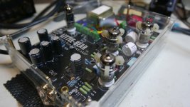
I think I'm in need of some help here by any electronics experts. I've had this Little Bear T10 Pro 2.5 Phono Preamp with 12ax7 Telefunken tubes for about a year now and been enjoying it. Then I figured I would have some fun, take advantage of all the big sales Parts ConneXion is offering and buy all new exotic capacitors and resistors. My 1st step was just to replace two of the .47uf 450v caps with MUNDORF - MEAIO-0.47, 0.47uF 450V, Mcap EVO Oil Series and the two of the AMTRANS- 100pF, 100VDC, AMCH Polypropylene Film Cap and AMTRANS - 0.1uF 630V, Amtrans AMCO Metalized Polyester (PET) Caps.
Success@! Sounded great with no problems. My soldering skills are good enough.
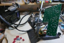
But then I attempted to do the entire signal side by replacing all the resistors and caps. That's when disaster stuck! I was dumb enough NOT to test all the new parts with my multimeter before soldering them in. For some reason I trusted the supplier that they would test these resistors. After I installed them all the phono preamp will not even power on. Dead. I started some tracing with my multimeter to see if I had a cold solder socket. Then realized I better test the values of these resistors and caps. Sure enough all the 3M3's and the 330K resistors either had no resistance value at all or measures 50% of what they are rated.
Also, I was told that I should never have installed the 330k carbon KIWAME Resistors 330K / 2 watt, 1.0%, Axial on the power rails of R15 and R23. That they would melt or something.
If that is correct, then I understand where I went wrong. But why are all the 3.3 meg resistors fail too? Are those power? Did I get them watt rated high enough? 0.5 (1/2) Watt?
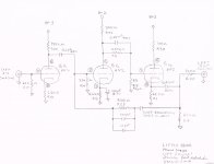
Below I listed all the parts I ordered to replace the signal side of the preamp. All the positions are only for the Right Channel. Just double everything for both channels. Here is a link to Coffee's file of the right channel schematic from the Vinyl Engine.
Domesticating & Documenting the Little Bear - Vinyl Engine
One more thing, I soldered everything at 430 degree F. With Wonder Solder. Help desperately needed.
Location: Near R23 - MUNDORF - MEAIO, 0.47uF 450V, Mcap EVO Oil Series
Location: Near R9 - SMICA - SILVER MICA 300pf 500V CAPACITOR
Location: Near R9 - SMICA - SILVER MICA 10pf 500V CAPACITOR
Location: Near R9: - AMTRANS- 100pF, 100VDC, AMCH Polypropylene Film Cap, gold-plated OFHC Leads
Location: Near R15: - AMTRANS - 0.1uF 630V, Amtrans AMCO Metalized Polyester (PET) Caps, gold-plated OFC
Location: R24 - KIWAME Resistor 220R / 2 watt, 1.0%, Axial, Tinned Copper Leads, Flameproof Silicone Coated
Location: R8, R6, R3, R10, R12, R14 - PRP Resistor 3M3 / 0.5 (1/2) Watt, Metal Film, 1%, 100ppm, Non-Magnetic – All failed
Location: R9 - KIWAME Resistor 910R / 2 watt, 1.0%, Axial, Tinned Copper Leads, Flameproof Silicone Coated
Location: R18, R11 - KIWAME Resistor 2K2 / 2 watt, 1.0%, Axial, Tinned Copper Leads, Flameproof Silicone
Location: R16, R5, R2 - KIWAME Resistor 62K / 2 watt, 1.0%, Axial, Tinned Copper Leads, Flameproof Silicone
Location: R7 - PRP Resistor_62499 100R / 1 Watt , Metal Film, 1%, 100ppm
Location: R15, R23 - KIWAME Resistor 330K / 2 watt, 1.0%, Axial, Tinned Copper Leads, Flameproof Silicone – All failed
Success@! Sounded great with no problems. My soldering skills are good enough.
But then I attempted to do the entire signal side by replacing all the resistors and caps. That's when disaster stuck! I was dumb enough NOT to test all the new parts with my multimeter before soldering them in. For some reason I trusted the supplier that they would test these resistors. After I installed them all the phono preamp will not even power on. Dead. I started some tracing with my multimeter to see if I had a cold solder socket. Then realized I better test the values of these resistors and caps. Sure enough all the 3M3's and the 330K resistors either had no resistance value at all or measures 50% of what they are rated.
Also, I was told that I should never have installed the 330k carbon KIWAME Resistors 330K / 2 watt, 1.0%, Axial on the power rails of R15 and R23. That they would melt or something.
If that is correct, then I understand where I went wrong. But why are all the 3.3 meg resistors fail too? Are those power? Did I get them watt rated high enough? 0.5 (1/2) Watt?
Below I listed all the parts I ordered to replace the signal side of the preamp. All the positions are only for the Right Channel. Just double everything for both channels. Here is a link to Coffee's file of the right channel schematic from the Vinyl Engine.
Domesticating & Documenting the Little Bear - Vinyl Engine
One more thing, I soldered everything at 430 degree F. With Wonder Solder. Help desperately needed.
Location: Near R23 - MUNDORF - MEAIO, 0.47uF 450V, Mcap EVO Oil Series
Location: Near R9 - SMICA - SILVER MICA 300pf 500V CAPACITOR
Location: Near R9 - SMICA - SILVER MICA 10pf 500V CAPACITOR
Location: Near R9: - AMTRANS- 100pF, 100VDC, AMCH Polypropylene Film Cap, gold-plated OFHC Leads
Location: Near R15: - AMTRANS - 0.1uF 630V, Amtrans AMCO Metalized Polyester (PET) Caps, gold-plated OFC
Location: R24 - KIWAME Resistor 220R / 2 watt, 1.0%, Axial, Tinned Copper Leads, Flameproof Silicone Coated
Location: R8, R6, R3, R10, R12, R14 - PRP Resistor 3M3 / 0.5 (1/2) Watt, Metal Film, 1%, 100ppm, Non-Magnetic – All failed
Location: R9 - KIWAME Resistor 910R / 2 watt, 1.0%, Axial, Tinned Copper Leads, Flameproof Silicone Coated
Location: R18, R11 - KIWAME Resistor 2K2 / 2 watt, 1.0%, Axial, Tinned Copper Leads, Flameproof Silicone
Location: R16, R5, R2 - KIWAME Resistor 62K / 2 watt, 1.0%, Axial, Tinned Copper Leads, Flameproof Silicone
Location: R7 - PRP Resistor_62499 100R / 1 Watt , Metal Film, 1%, 100ppm
Location: R15, R23 - KIWAME Resistor 330K / 2 watt, 1.0%, Axial, Tinned Copper Leads, Flameproof Silicone – All failed
Last edited:
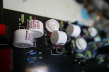
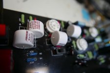
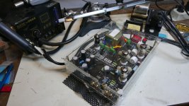
Photo of the caps and resistors and the old parts pile.
Jpeg files too large. Man, what a pain
Attachments
Ok, I had a 2 hour phone call with the master electronic engineer over at Sonic Craft in Texas. He has been designing and building circuits for 25 years. He s very knowledgeable and a pleasure to talk to. He looked at the power supply circuit schematic and said some things. First, he suggested that it sounds like my rectifier died. Which, by looking at this circuit design will happen again. Sure enough, I replaced it and the phono preamp fired right up. I put it back into my sound system and played it for two hours. Sounded wonderful. Much more lush, resolving and just simply bigger.
These are my notes based on our phone conversation.
The highest power rail on this preamp is B3. it is dissipating .22 watts. 1/4 watt is good enough. Max 250v for a 1/4 watt resistor.
I had installed Kiwame 2 watt resistors which was MORE than enough. Rated for 1500v. So didn’t need a wirewound resistor.
Kiwame is a very modern resistor. No drift since the power supply is unregulated. How it sounds is more a consideration. Wirewound resistors is more stabile than carbon film. Doesn’t mean that all wire resistors are good.
Different resistors....just different requirements.
Suggested to use a Takman REX 1/2 watt instead for half the price. But what I have is fine. No sense ripping out what I already installed.
Power supply schematic notes:
The reason the rectifier goes out is because the 1st cap at B+3 is 100 uF 450v
Because the tube lives roughly half of its life. The 100uF is really hard on the rectifier. But it is great at filtering. It would be nicer to have more filtering.
To have the rectifier tube to work in its mean the solution is to change this tap to 47uF. Im not shopping for a nice 47uF capacitor.
He mentioned that for Electrolytic caps. Panasonic ed or ee would be fine.
Can be 350v+
---------------
So, after 2 hours of playing the phono preamp shut itself off and when I tried to power the preamp back on again it turned on and played but sounded all harsh and static noisy. I will try playing again tonight. I am going to order that new Cap as he suggested. He said that existing 100uF cap will eat up rectifiers like candy.
Also, I'm going to recheck the transformer leads again and make sure they are wrapped well around the transformer and connected to the terminals
Also, he said there is a much better dual transformer for $23 that would be a drop in replacement. I'm going to look into that as well.
- Status
- This old topic is closed. If you want to reopen this topic, contact a moderator using the "Report Post" button.