I occasionally help out a local college radio station with engineering. Among other things, I have constructed a couple of RIAA preamps for their production and master studios. It's not exactly an audiophile operating environment. For the main production studio, I designed and built a preamp based on the passive equalization circuit shown in "A". The front end amplifier U1 was an LT1115, and the post amplifier 1/2 of an OPA2134. This fed another OPA2134 buffer and a DRV134 balanced driver. All the guts for one turntable fitted on a small (~3" X 4") circuit board. To my chagrin, the noise performance of this circuit was less than spectacular, with very audible hiss in the monitor speakers when the pot on the mixing board was turned up all the way. However, the preamp sounded nice, with tight bass and well-articulated midrange and highs. As an experiment, I plugged an RCA plug terminated with the cartridge equivalent resistance into one of the input jacks - presto, no noise, zip, zero, even with the slider on the mixing board pushed up all the way. I was forced to conclude that the problem might be with the TT cartridge. The most common broadcast cartridge is a Stanton 500 or 680. These have an inductance of ~900mH (!) and about 1250 ohms resistance. I decided as a preliminary hypothesis that the noise current of the first op amp was interacting with the inductance to produce the noise. I replaced the first opamp with a FET input OPA134, and the noise mostly went away, though the overall sound became more "constricted". Can anyone recommend a better FET input amp (single) that I can use in the first stage? I am considering an AD745JN (if I can find some) or an OPA627.
To get around the bias and noise current problem for the main studio preamps, I used a passive setup with the gain block shown in "B", feeding AD826 buffers and DRV134 balanced drivers. This has been more or less successful, though it's a lot more parts. Has anyone had similar experiences in a broadcast environment?
To get around the bias and noise current problem for the main studio preamps, I used a passive setup with the gain block shown in "B", feeding AD826 buffers and DRV134 balanced drivers. This has been more or less successful, though it's a lot more parts. Has anyone had similar experiences in a broadcast environment?
Attachments
i've always been curious about "passive eq" between 2 op amp based feedback gain blocks - what's the theory?
you are using feedback around the op amps to provide flat gain when the op amp gain inherently rolls off with a first order slope - wether you subscribe to the classic feedback theory maximum loop gain principle or to Otala's phase intermodulation distortion/TIM camp, both lines of reasoning suggest that puting a riaa lp pole in the feedback network will give better results
perhaps the opa134 will sound less "constricted" with a feedback cap implementing one of the riaa poles and providing a large region of constant loop gain where the riaa rolloff and the op amp open loop gain rolloff compensate each other - additionally the slew rate demand is hugely reduced
the zero intoduced when the noninvering circuit reaches unity gain is easily compensated by a passive interstage rc if you beilve it necessary, Thorstein actually recomends a hf zero as being desireable to cancel the cutting head amp rolloff
If you pose your question about equalization in another thread, I'm sure you'll get all the answers you want. There are more combinations of feedback and passive equalization than a cat has hair... I chose the simplest implementation of passive equalization.
The main thrust of this thread was not the equalization scheme of the preamp, but the fact that using an opamp with the second lowest noise performance in the world was not enough to get adequate noise performance with a broadcast standard cartridge like the Stanton 680. This appears to be due to interaction of the cartridge inductance with a bipolar amplifier's bias current. Terminating the pramp inputs with the equivalent resistance of the cartridge completely got rid of the noise. Changing the amplifer from a LT1115 (bipolar input, high bias current) to an OPA134 (FET input, low bias current) drastically reduced the noise level of the preamp, at the cost of an altered sound palette. I will be looking for a more pleasing op amp to replace the OPA134, which doesn't exactly have the lowest noise specs or the best sound. An AD745 would probably be wonderful, if I could find some through-hole parts. Though not as quiet, an OPA627 is another possibility, though I am reluctant to cough up the cash it would take to replace the four input amps in the preamp package as an experiment.
There are other implications of using a cartridge with a high inductance. One of them is that there is a big interaction between the cartridge inductance and any stray cable and input capacitance. The cartridge termination resistance needs to be carefully tailored to avoid resonant peaks or drastic high frequency rolloff. Using the standard termination resistance and capacitance mentioned in the cartridge data sheet just just doesn't cut it. This interaction means you also have to be very careful what you do to protect the preamp inputs from RF. Extra capacitance is a bad idea for the aforementioned reasons. Perhaps a high frequency common mode choke is the best one can do.
For the master studio setup, I actually did capacitance measurements on the output cables of the Technics SL1200 turntables we use. They measure out at about 50pF a side. I loaded this value and the cartdidge characteristic impedances into PSpice and got an optimum termination resistor of about 60k. This allowed the high frequency response to be flat or very slightly peaked, but unfortunately still with a lot of rolloff past 10kHz.
Grado has a relatively new line of DJ cartridges using their moving iron technology that have some promise due to their drastically lower inductance and resistance (50mH vs. 900mH). However, the stylus cantilever in the Grado cartridges looks less robust than the Stantons. This a real consideration, as the turntables in the master studio get used 24/7. When I tried Grados in the studio as an experiment, the DJs had trouble back cueing. This may be a function of the anti-skate and pressure settings, and will have to be revisited.
Perhaps the best way to deal with cartridges like the Stanton would be a differential scheme similar to the Jung/Wurcer RIAA preamp. This means that the cartridge sees only the offset current from the differential amp rather than the whole bias current, greatly reducing that source of noise. Common mode crap rejection would be better, too. If the output cable returns of the Technics TTs are only conected to the cartridges, it would be worth a shot. Anything requiring modification of the turntables is out, because you lose interchangability.
BTW, I incorporated the 50kHz zero in the RIAA network for the master studio discrete preamp, but not in the earlier opamp preamp in the production studios (I didn't know about it then). I don't think It'll make much difference either way, as the cartridge cuts the highs anyway.
900mH? All the data I have for the Stanton 500AL states that it is 400mH.
Have you looked into Ortofon DJ cartridges?
I was under the impression that passive RIAA EQ was a bad idea and it is the worst configuration for noise and headroom. Although you have terminated the input and got little noise so proved that it's a cart interaction problem, have you tried any other pre-amps, just out of interest? Even a cheap one!
the AD797 datasheet is a bit light on the noise current discussion but the info is there if you know how to use it
the LT1115 ds is a bit better but both oversimplify by talking about source resistance instead of impedance
ancient national semi app notes help, look for an-104 and an-222
basically your mid band cart Z of ~ 10 KOhms has 2pA/rtHz noise current flowing in it from the AD797 input noise current giving 20 nV/rtHz (rising with source impedance)
on a total noise basis you would be better off with a TL071
but you really haven't established that the noise is an issue at all, without doing some numbers on cart sensitivity and system gain the hiss could easily be > 10-20 dB below record surface noise and you are just wasting everyone's time
my earlier point was that your circuit topology is very poor by most recognized criteria, the "simplicity" of the schematic is an artifact of human visual perception or function block style thinking and doesn't reflect the performance limitaions of the op amp gain blocks in the compelte circuit context
i find calculating the pole location in a op amp gain block with a feedback cap rather simple, parts count is actually lower and performance is objectively better
To richie00boy - the Stantons 680s do really have 930mH inductance. We used to use the 500ALs in the studios (cheap, cheap), but upgraded to the 680s a few years back, as they sound a little better. Ortofons have been considered as replacements, but the cartridges and replacement styli are both really expensive. They also are prized, well-known, and distinctive DJ items and likely to take a walk - sad but true. This wouldn't be a problem in the master studio, as it is occupied 24/7, but the production studios are another matter. The Grado DJ1000s are a lot less expensive ( about the same as 680s), look like normal cartridges, and aren't widely known just yet. They should also sound loads better than any of the other common broadcast/DJ cartridges.
I may decide to move the RIAA 75usec roll off to the first amplifier if I can find a way to retrofit neatly on the existing boards. Given the splendid high frequency output of the Stantons (grin), it may not make a lot of difference. If I can get the Grados to work, it will be another story. If you have access to simulation software, try setting up a simulation with the Stanton 680 impedances driven by a voltage source and terminated by the recommended resistance and capacitance - the results are pretty shocking.
To jcx - the noise from the preamp using the LT1115s was a few tens of millivolts p-p (broadband hiss) at the preamp output when it was terminated by a TT with the Stanton cartridge, The preamp gain is 40dB at 1kHz. With a 1.24k metal film resistive shunt placed across the inputs, the noise was unmeasurable (by an oscilloscope) at the preamp output and inaudible at the mixing console with the sliders up full. The topology I used may be the worst in your point of view, but it doesn't appear to be a major noise source. As I said to richie00boy, though, I may try rearranging things a bit, at least in the production studio preamp. Since the op amps in the preamp there are socketed, I can also try slipping in a few other choices to test. I want to try some NE5534s (briefly). Given their high bias current, they should really be noisy. The OPA134s I ended up using for the inputs were a cost compromise for a single FET input amplifier, still with better noise specs than the TL071, and lower overall noise than the LT1115. I don't think I can do better given the present setup without spending a lot of money. The preamps with the OPA134s have been humming along (poor choice of words) for about 6-7 months now with no other issues.
As I said in a previous post here, if I had it to do all over again, I would probably try using a differential amp at the preamp inputs, irrespective of topology.
BTW - you knock the topology I used, but you should have seen the ancient rubbish that was in the studios before...
Someone needs to revive the old National Semi app note on the equivalent noise impedance of MM cartridges. If you look at the real part of the impedance at high frequencies the noise current of low noise bipolars is a real problem. Indeed the AD745 (or OPA627) would do the trick in this case. I designed the AD745 and I have trouble getting any, unfortunately they've been transfered to another business unit. One of our guys used to DJ for KLAX and he has 745's in his home system. Both of us are big supporters of college radio here in the Boston area, maybe we could find a couple of DIPs in our junk boxes.
scott wurcer said:Someone needs to revive the old National Semi app note on the equivalent noise impedance of MM cartridges. If you look at the real part of the impedance at high frequencies the noise current of low noise bipolars is a real problem.
Hi Scott, i'm having a problem with "look at the real part of the impedance", if this refers to the cart/source impedance.
the noise current flows in the total impedance of the source and, unfortuanantly the imaginary part of the Z_source*i_noise is "real" noise voltage - the Magnitude of the impedance at a given freq has to be used to calc the spot voltage noise level due to the noise current at that freq
Dear ladies and gentlemen,I occasionally help out a local college radio station with engineering. Among other things, I have constructed a couple of RIAA preamps for their production and master studios. It's not exactly an audiophile operating environment. For the main production studio, I designed and built a preamp based on the passive equalization circuit shown in "A". The front end amplifier U1 was an LT1115, and the post amplifier 1/2 of an OPA2134. This fed another OPA2134 buffer and a DRV134 balanced driver. All the guts for one turntable fitted on a small (~3" X 4") circuit board. To my chagrin, the noise performance of this circuit was less than spectacular, with very audible hiss in the monitor speakers when the pot on the mixing board was turned up all the way.
However, the preamp sounded nice, with tight bass and well-articulated midrange and highs. As an experiment, I plugged an RCA plug terminated with the cartridge equivalent resistance into one of the input jacks - presto, no noise, zip, zero, even with the slider on the mixing board pushed up all the way. I was forced to conclude that the problem might be with the TT cartridge. The most common broadcast cartridge is a Stanton 500 or 680.
These have an inductance of ~900mH (!) and about 1250 ohms resistance. I decided as a preliminary hypothesis that the noise current of the first op amp was interacting with the inductance to produce the noise.
I replaced the first opamp with a FET input OPA134, and the noise mostly went away, though the overall sound became more "constricted".
Can anyone recommend a better FET input amp (single) that I can use in the first stage? I am considering an AD745JN (if I can find some) or an OPA627.
To get around the bias and noise current problem for the main studio preamps, I used a passive setup with the gain block shown in "B", feeding AD826 buffers and DRV134 balanced drivers. This has been more or less successful, though it's a lot more parts. Has anyone had similar experiences in a broadcast environment?
very interesting thread and observations. But I have some questions:
1) Do you remember, whether your mentioned audible hiss was above or below typicall record surface noise, which depends also on footprint of stylus (e. g. shibata, elliptical or hyper elliptical profiles) so as the selected tracking forces.
2) By using the topology as described in the URLs from post #1 under
http://www.diyaudio.com/forums/anal...stage-working-inverted-mode-not-find-why.html
such interaction between input stage and inductance of the cartridge can be avoided, so I think. Are my estimate right ?
3) I don't understand this term: overall sound became more "constricted"
Thank you for advices.
1) I would not want the cartridge impedance interacting with the gain resistors
2) The noise was subjective. If you pot up the microphone sliders on the same mixing board to the same relative position, no hiss. Surface noise or no, I would have been snowed under with dreck by my peers unless the performance was the same. It was also maddening that the second quietest opamp on the planet was so noisy in that application.
3) The OPA134 sounded subjectively worse. The difference was immediately apparent, that "something doesn't sound right" that is the kiss of death. The AD745s from Mr. Wurcer didn't have those issues and are still in place to this day (thanks, Scott...)..
The second circuit I show in the first post, used in the master studio preamps, is fatally flawed in retrospect. It will be replaced in a few months by a much simper circuit that will likely kick its spotty behind re listenability.

Some users claim, that this model together with the AD743 is still the best available integrated operational amplifier for MM/MI RIAA phono preamps. LC-Audio also think so - go toSomeone needs to revive the old National Semi app note on the equivalent noise impedance of MM cartridges. If you look at the real part of the impedance at high frequencies the noise current of low noise bipolars is a real problem. Indeed the AD745 (or OPA627) would do the trick in this case. I designed the AD745 and I have trouble getting any, unfortunately they've been transfered to another business unit. One of our guys used to DJ for KLAX and he has 745's in his home system. Both of us are big supporters of college radio here in the Boston area, maybe we could find a couple of DIPs in our junk boxes.
L C Audio Technology / RIAA/MC Amplifier
(last image)
Unfortunately no simplified schematic I can find in the datasheets - go to
https://www.analog.com/media/en/technical-documentation/data-sheets/ad745.pdf
https://www.analog.com/media/en/technical-documentation/data-sheets/ad743.pdf
Is it similar to those from AD825/AD829/AD817 (only one voltage gain stage as folded cascode and buffer stage) ?
AD817 is in use in the Graham Slee RIAA stage:
Vinyl Asylum
And what about with a AD797 with 2SK389 or other dual jFET at the inputs ? - go to page 9+10 under
http://www.cordellaudio.com/JFETs/LSK489appnote.pdf
Last edited:
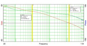
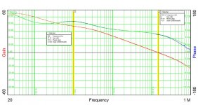
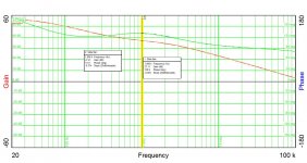
Here's the next rev of TT preamps for the KFJC main studios. The overall sense of the preamp is inverting, but I'll be switching around the leads on the output transformer for non-inverting response overall. Output transformers are Reichenbach RE 11-DM
Attachments
Here are the response curves for the three modules that are going into the preamp box, each representing two channels of RIAA amplification/equalization plus a unity gain line driver, Response curves line up in a rather satisfying way...
Attachments
Some users claim, that this model together with the AD743 is still the best available integrated operational amplifier for MM/MI RIAA phono preamps. LC-Audio also think so - go to
L C Audio Technology / RIAA/MC Amplifier
This is stolen from Leach:
A company copied the design without my permission and marketed it. The company name was Markof. When I first heard of this, I asked Gene Pitts if he knew anything about the company. By coincidence, he had just received a Markof head amp for test. He mailed it to me. I opened it up and found the circuit to be the same as mine with one exception. 300 ohm resistors had been added in series with the emitters of the two transistors for bias stabilization.
In 2003, a second company has copied the design. The name of the company is LC Audio Technology. They called it a "current-to-voltage" transformer. To power the preamp, they used photo cells illuminated with an incandescent bulb . They refered to the circuit as "a clone of the famous 1970's step up, that transforms the currents from the cartridge coil,..."
See:
Moving Coil Cartridge Head Amps
I'm way past using the LT1115 - that was years ago. The problem was the bias current of the IC (considerable) interacting with the high (almost a Henry). Using an AD745 fet input opamp instead of an LT1115 fixed the problem dead to rights, Ind I haven't changed anything in that particular preamp circuit since. That reramp is used in our production studio - the circuit shown in post 13 will be the one I use in the master studio going froward.
Last edited:
This is stolen from Leach:
A company copied the design without my permission and marketed it. The company name was Markof. When I first heard of this, I asked Gene Pitts if he knew anything about the company. By coincidence, he had just received a Markof head amp for test. He mailed it to me. I opened it up and found the circuit to be the same as mine with one exception. 300 ohm resistors had been added in series with the emitters of the two transistors for bias stabilization.
In any case if he didn't patent it he has no claim for damages.
- Home
- Source & Line
- Analogue Source
- Broadcast RIAA Blues