In the same vein as 6L6's MK2 thread, I thought we should start one for a related, formidable, Technics beast.
There's not a lot of information out there on these, even if you can read Japanese, or want to try your luck at deciphering Google Translate... Sometimes I think reading Japanese would be easier.
Should any pertinent links or information come up, I'll try to document them in this first post. Skip down to get to the good stuff.
-------------------------------------------------
This is my next project, (relatively) fresh from Japan. Aside from some small scratches and dings in the chassis, a dent in the top of the control box, and a platter in desperate need of some polish, it's in better shape than I thought.
After unboxing and throwing on the platter, I put it on my step-down converter and gave it a spin. I'm pleased to report that everything is working as it should. I did notice some green legged caps in controller, so ~30 seconds is all I'll do until I finish the refurb. I didn't really want to run it at all, but I had to make sure it was as advertised and the listing pictures showed it powered on, so I took the chance.


After unboxing and throwing on the platter, I put it on my step-down converter and gave it a spin. I'm pleased to report that everything is working as it should. I did notice some green legged caps in controller, so ~30 seconds is all I'll do until I finish the refurb. I didn't really want to run it at all, but I had to make sure it was as advertised and the listing pictures showed it powered on, so I took the chance.
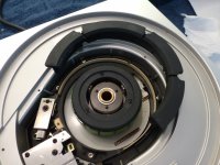
While I'm waiting for my parts order, I decided to take a look at the bearing.
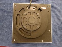
To remove the back cover, remove all the screws. Unlike the MKII/2A, they're all the same, and are self-tapping. The back cover is a composite material similar to the sub-plinth on the 1200MK2. There is a rubber gasket, so you need to get a good grip and give it a shake or two for it to break loose.
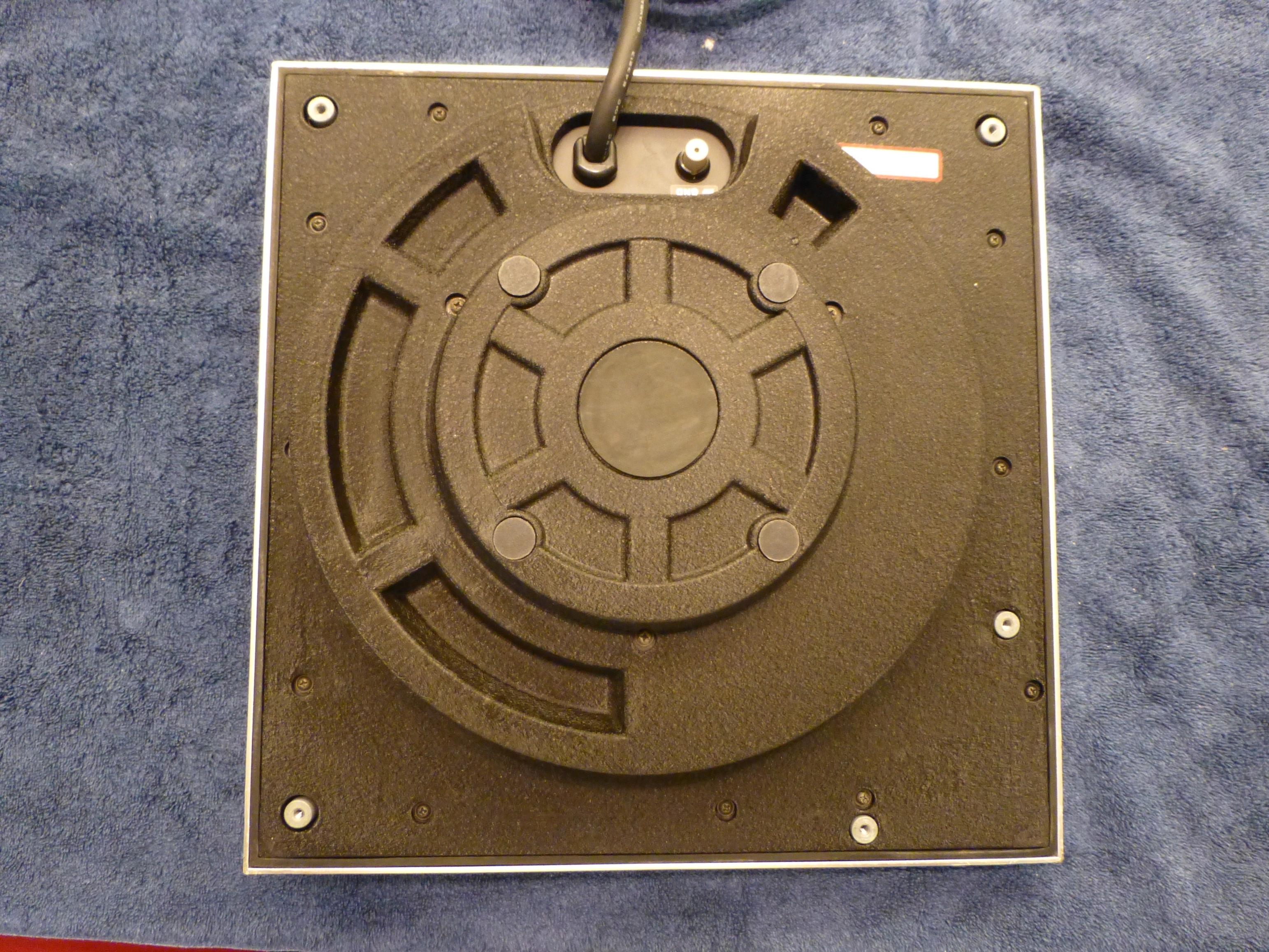


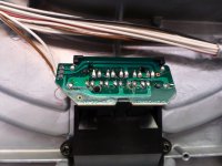
Some of the soldering leaves a lot to be desired.

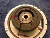
Start/Stop and speed switch mechanism.
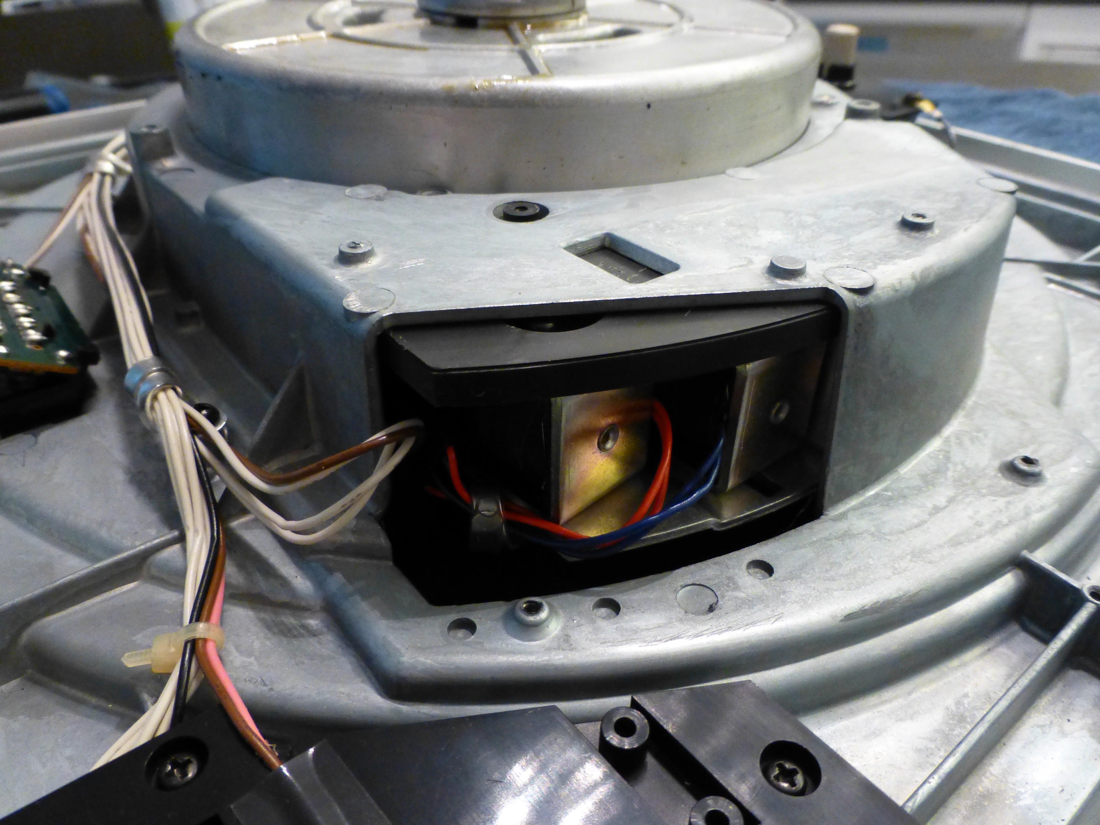
Dual brake solenoids. One is for a band brake like the MKII/2A, and the other is a lever brake.
To remove the back cover, remove all the screws. Unlike the MKII/2A, they're all the same, and are self-tapping. The back cover is a composite material similar to the sub-plinth on the 1200MK2. There is a rubber gasket, so you need to get a good grip and give it a shake or two for it to break loose.
Some of the soldering leaves a lot to be desired.
Start/Stop and speed switch mechanism.
Dual brake solenoids. One is for a band brake like the MKII/2A, and the other is a lever brake.
Attachments


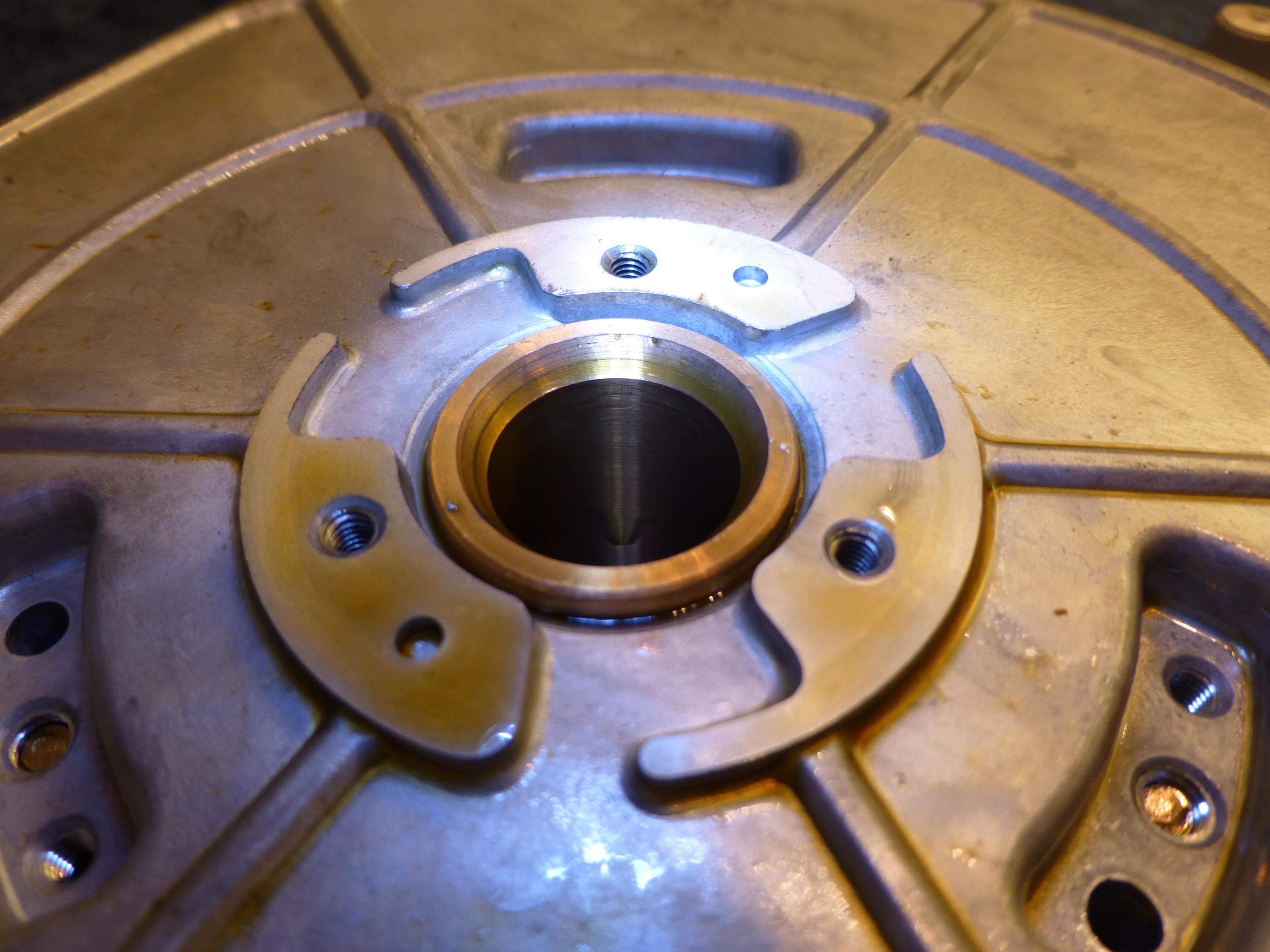
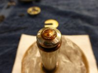
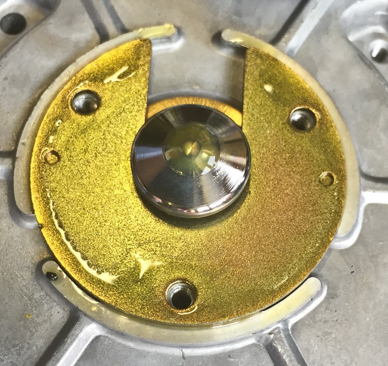
The bearing thrust cap on this 'table is open, so one consequence of over lubrication is that the oil leaks out.
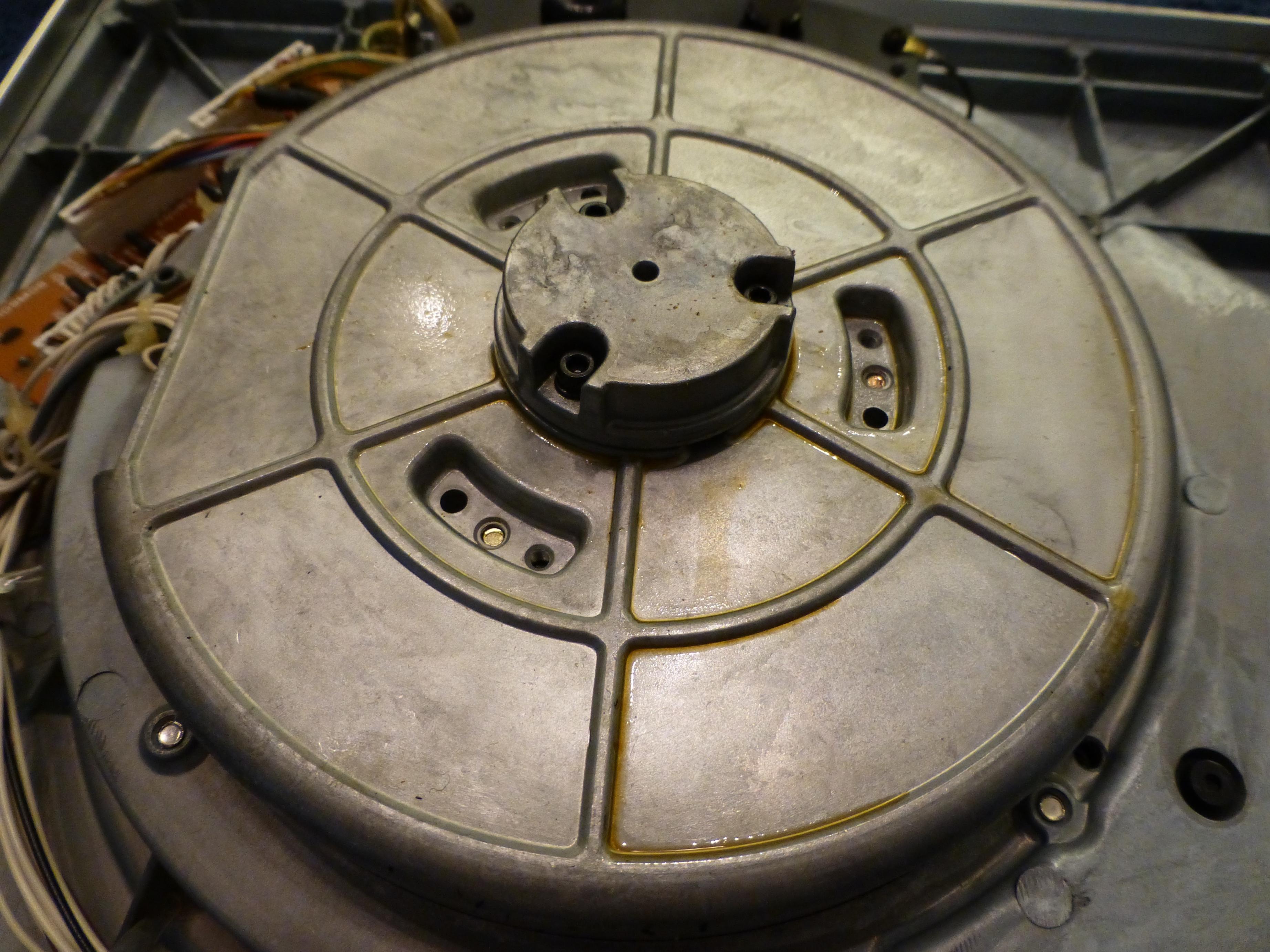
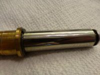
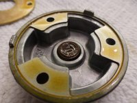
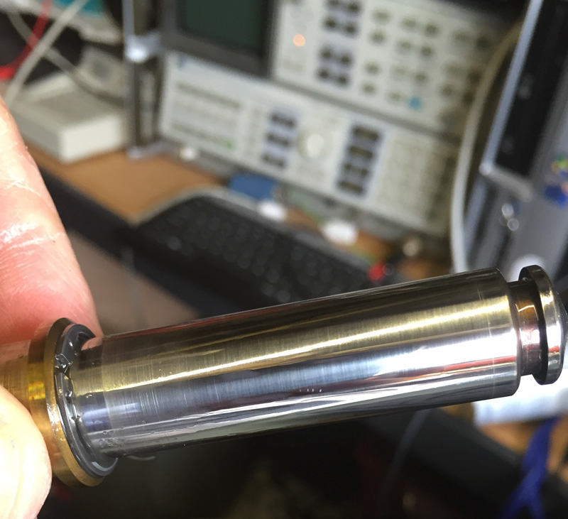
A 2.5mm hex key for the three socket head cap screws will liberate the bearing cap. From there the "C" retainer slides right off, freeing the shaft which you can pull out from the top-side.

On this one the wear on the shaft and bore appear to be very minimal, and I noticed the fit is very tight. Just with light oil there's enough resistance that you'd think it was lubricated with light grease.
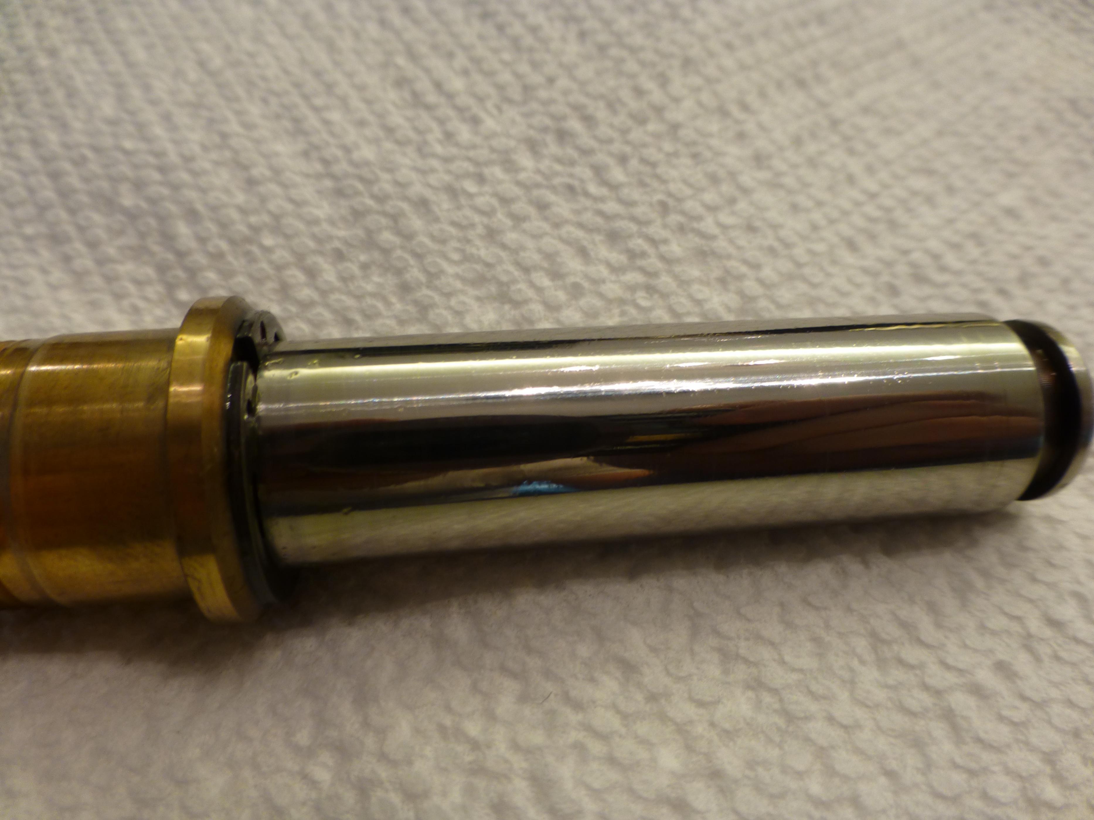
Now, the one thing that perplexes me is that I'm used to seeing light machine oil, which I presume is similar to the Technics oil, become gummy and amber in color when it's old. The only sign of oil not being oil anymore here is at the thrust bearing. However, this stuff has a consistency more like light grease than old gummy oil. This could be the way the Technics oil breaks down, or this could be some kind of grease only on the thrust bearing. Any ideas?

A 2.5mm hex key for the three socket head cap screws will liberate the bearing cap. From there the "C" retainer slides right off, freeing the shaft which you can pull out from the top-side.
On this one the wear on the shaft and bore appear to be very minimal, and I noticed the fit is very tight. Just with light oil there's enough resistance that you'd think it was lubricated with light grease.
Now, the one thing that perplexes me is that I'm used to seeing light machine oil, which I presume is similar to the Technics oil, become gummy and amber in color when it's old. The only sign of oil not being oil anymore here is at the thrust bearing. However, this stuff has a consistency more like light grease than old gummy oil. This could be the way the Technics oil breaks down, or this could be some kind of grease only on the thrust bearing. Any ideas?
Attachments


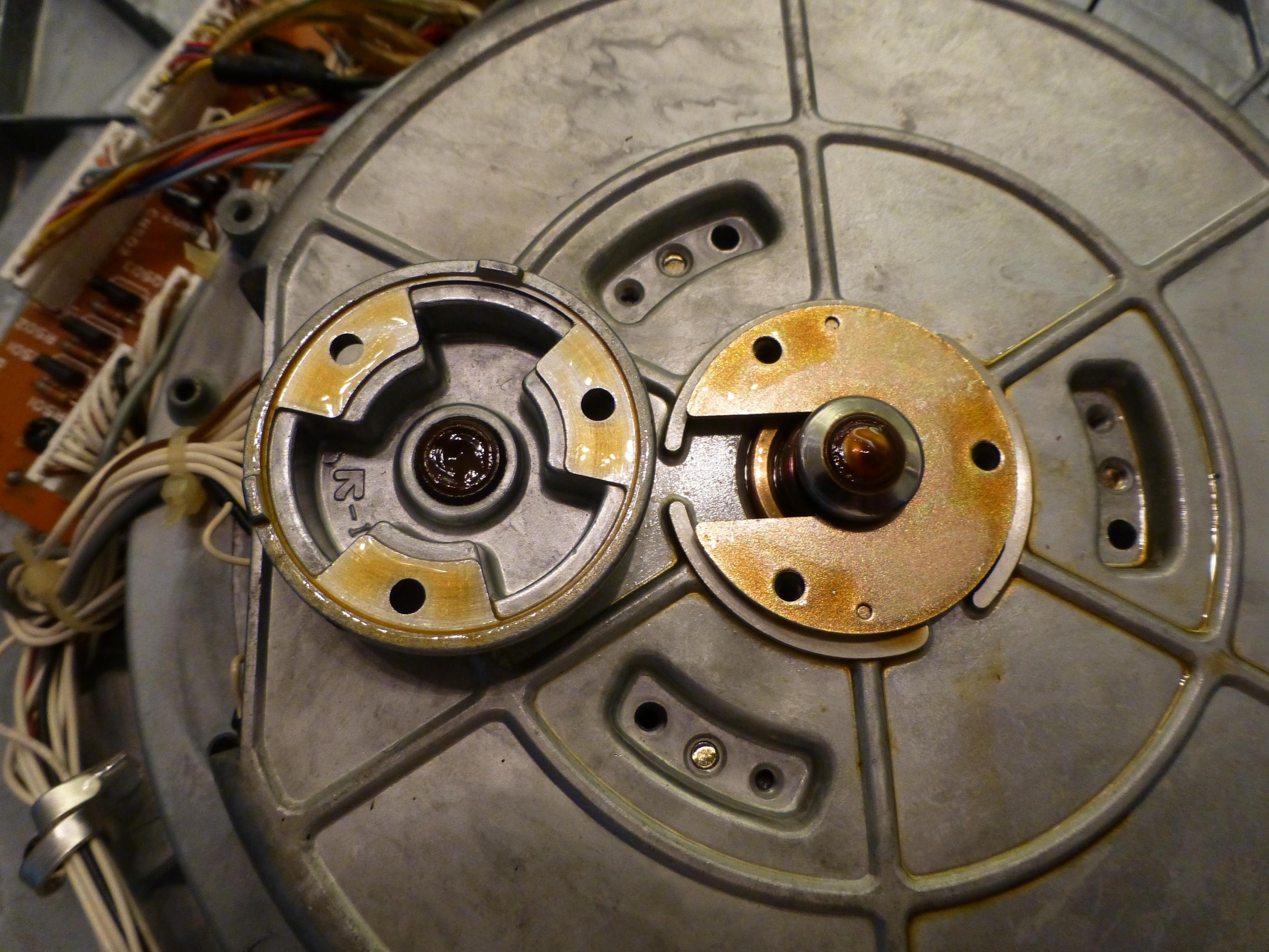
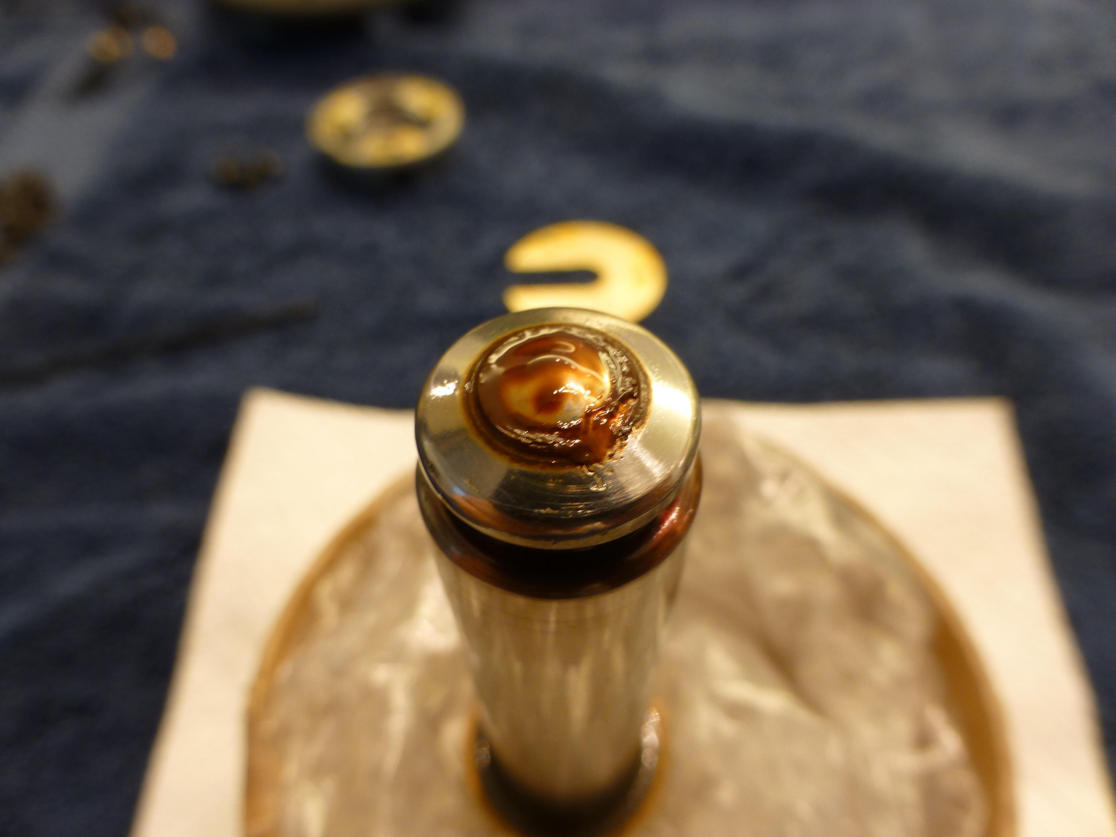
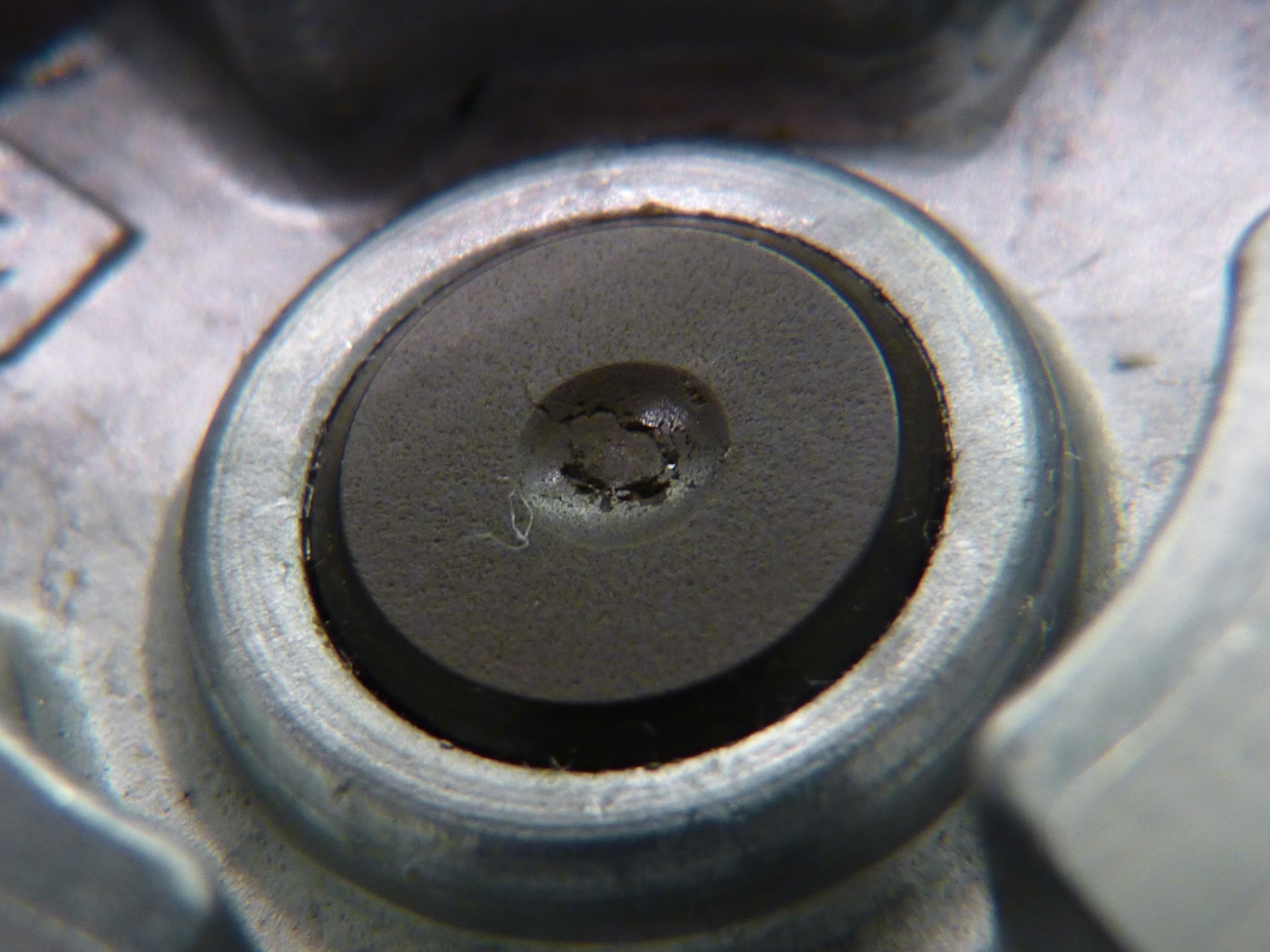
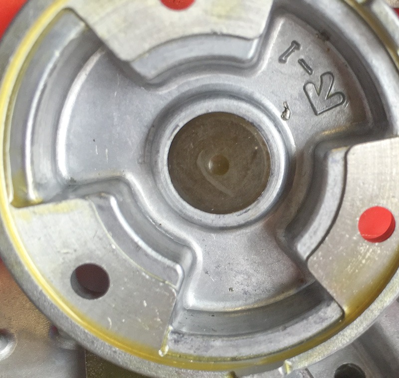
Mystery solved, unfortunately. The thrust bearing is ceramic, and the brown gunk is ground up bearing and oil. The ceramic on mine has taken and impact and has been damaged. Time to figure out how to replace it, and with what. I'm more than open to suggestions on this one...
Attachments

Thanks John for the steer on how to get the bearing apart.
Mine is here and showed little sign of wear with golden thin oil at the thrust pad. However I cleared everything out with IPA and cut the wedge brake corner off as it was dragging (I think) now the slight all but inaudible noise at 78rpm has completely gone. The bearing is very free and not tight with minimal drag.
There are some observations for others :
1. This is metric unit that uses mm Allen Keys and Philips heads (not posidrive, star or anything else)
2. The bottom cover, it needs to be re-fitted into the rubber gasket fully before screwing the screws back in, BUT :
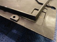
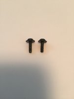
3. Two of the 15 cover screws are shorter with blunt ends (not pointed) these MUST go into the two holes very close to the big diameter of the inside base unit, in other words where they are close to the platter and will muck (f) it up if the long pointy ones are screwed in there, lucky I noticed !
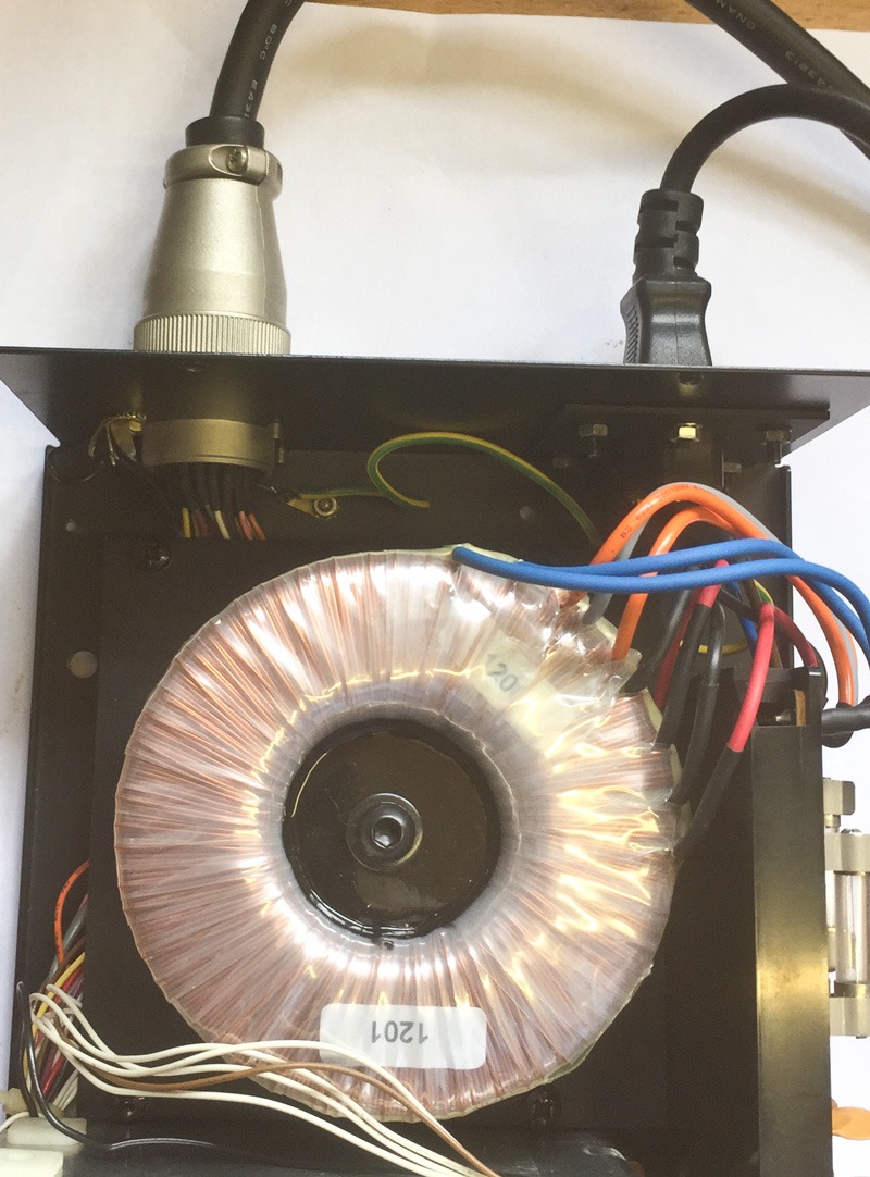
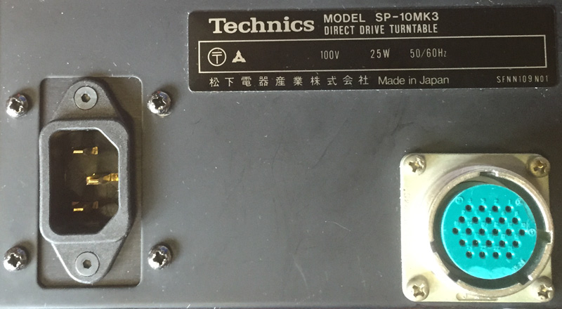
4. Most units are 100V the Japanese standard and they will not tolerate 117V let alone the up to 253 we get in the UK. So I had some custom toroids made and a new power inlet panel made to allow an IEC connector. The new transformer sits on a custom base plate spaced off the bottom to allow air through and fits to the original transformer mounting holes.
I have to hold my hand up, this is supposed to be for a customer, although he doesn't know it yet, he may get it or I may well decide to keep it !
BTW the MKIII has 15 poles the MKII 15 poles and the SL-1210 12 poles. I know, they were in eyesight all at the same time and counted using my fingers ! None of them suffer from pole induced flutter. They all have a proper tacho feed, not like described elsewhere !
Mine is here and showed little sign of wear with golden thin oil at the thrust pad. However I cleared everything out with IPA and cut the wedge brake corner off as it was dragging (I think) now the slight all but inaudible noise at 78rpm has completely gone. The bearing is very free and not tight with minimal drag.
There are some observations for others :
1. This is metric unit that uses mm Allen Keys and Philips heads (not posidrive, star or anything else)
2. The bottom cover, it needs to be re-fitted into the rubber gasket fully before screwing the screws back in, BUT :
3. Two of the 15 cover screws are shorter with blunt ends (not pointed) these MUST go into the two holes very close to the big diameter of the inside base unit, in other words where they are close to the platter and will muck (f) it up if the long pointy ones are screwed in there, lucky I noticed !
4. Most units are 100V the Japanese standard and they will not tolerate 117V let alone the up to 253 we get in the UK. So I had some custom toroids made and a new power inlet panel made to allow an IEC connector. The new transformer sits on a custom base plate spaced off the bottom to allow air through and fits to the original transformer mounting holes.
I have to hold my hand up, this is supposed to be for a customer, although he doesn't know it yet, he may get it or I may well decide to keep it !
BTW the MKIII has 15 poles the MKII 15 poles and the SL-1210 12 poles. I know, they were in eyesight all at the same time and counted using my fingers ! None of them suffer from pole induced flutter. They all have a proper tacho feed, not like described elsewhere !
Last edited:

If you have a japanese service guide I have a software mate who is bilingual.
Thanks! A friend tipped me off to an original North American service guide on eBay. Expensive, but well worth it IMO.
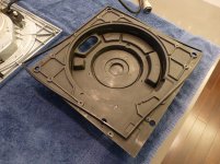
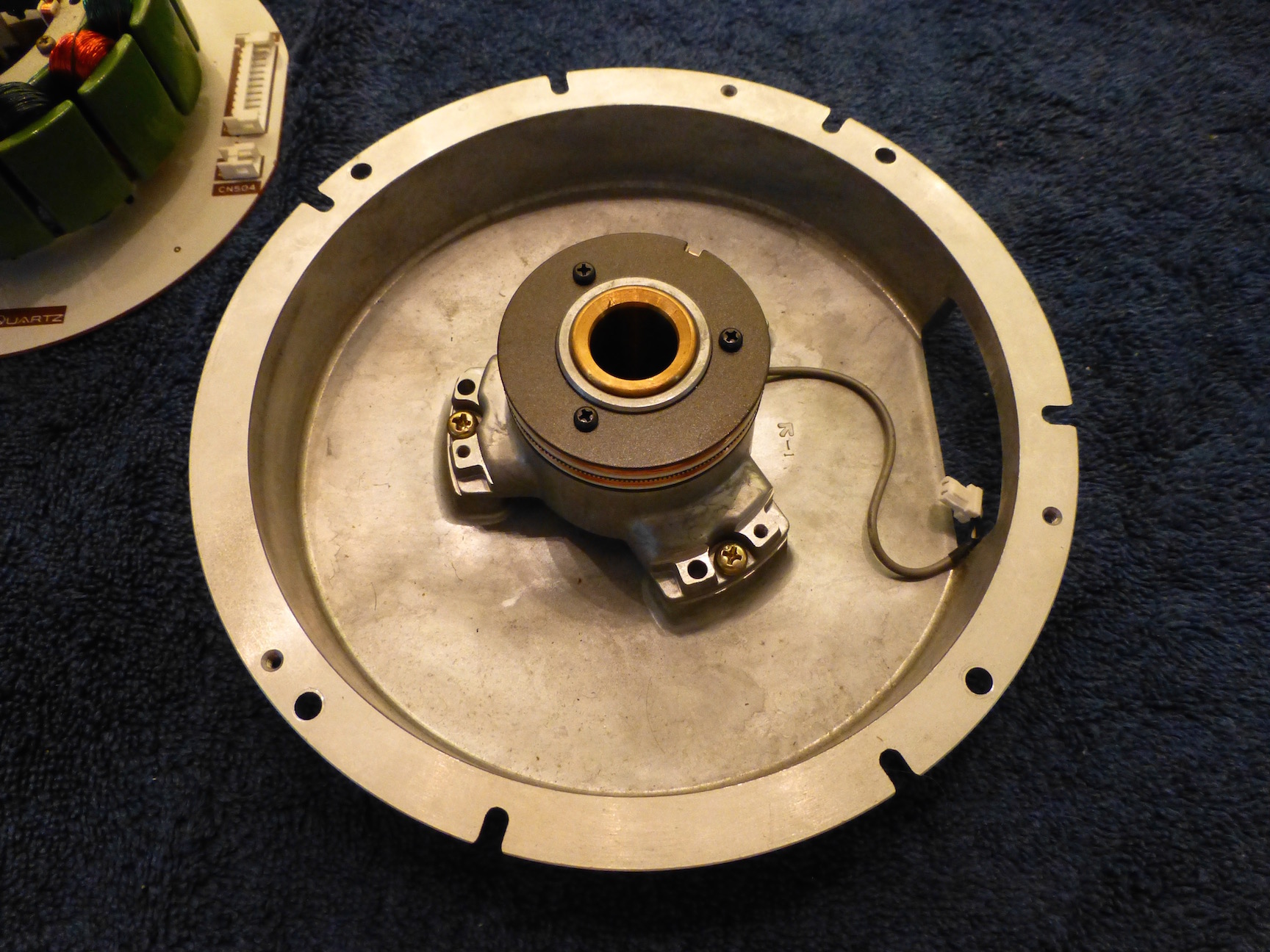
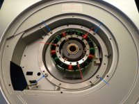
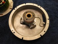
Last night I took apart the motor to inspect and clean it. After removing the plastic cover, simply pull out the rubber dampening block around the platter.

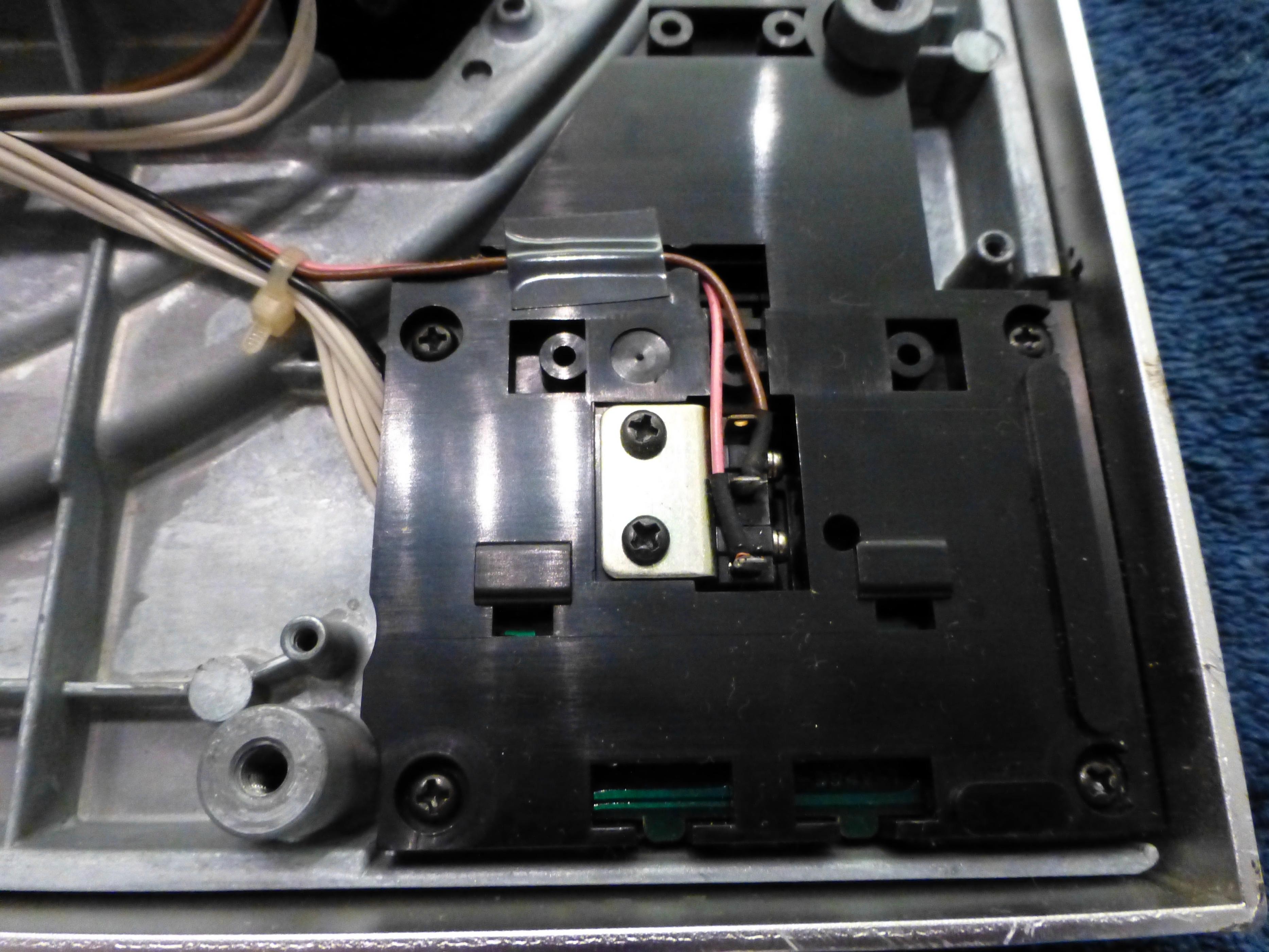
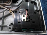
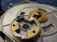
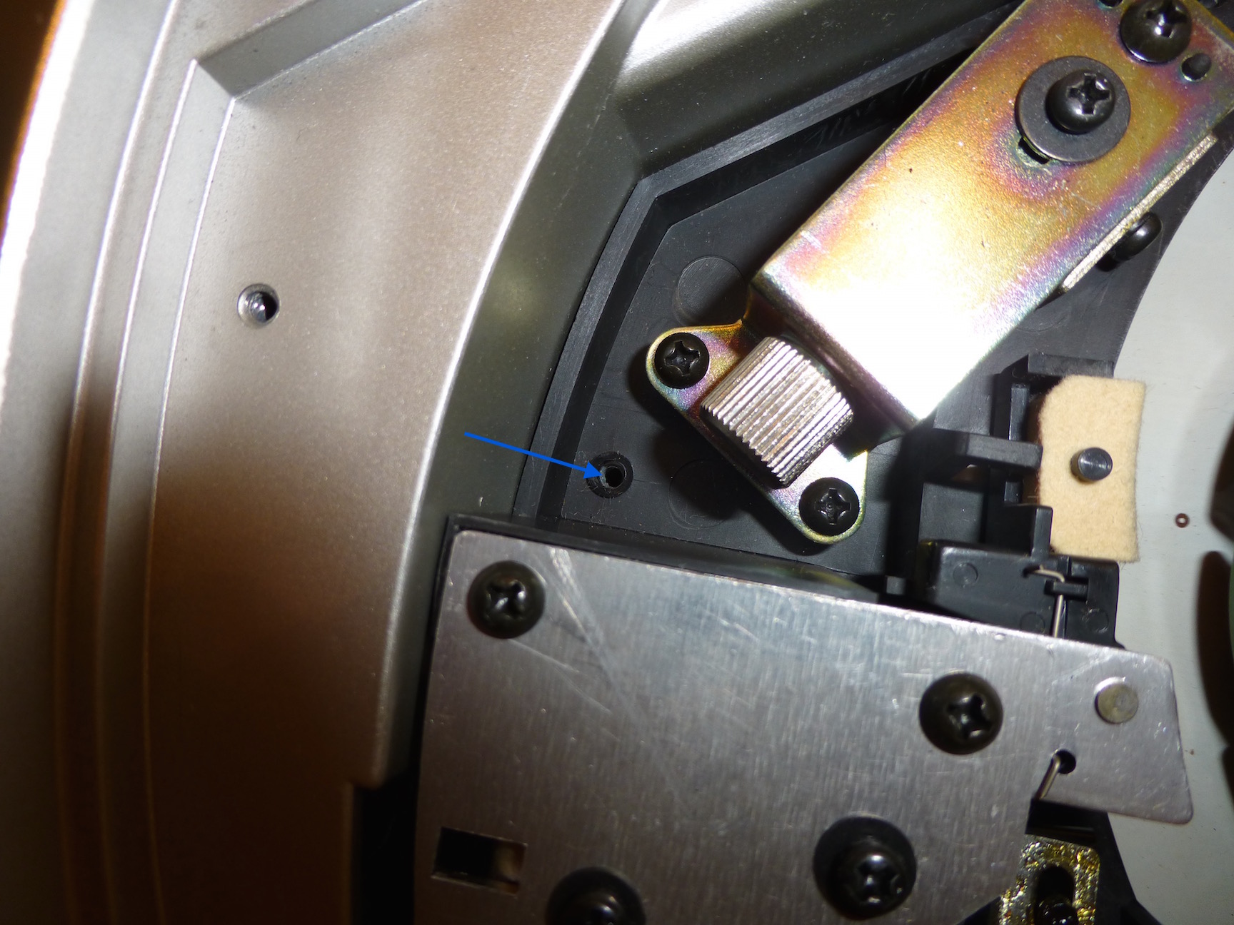
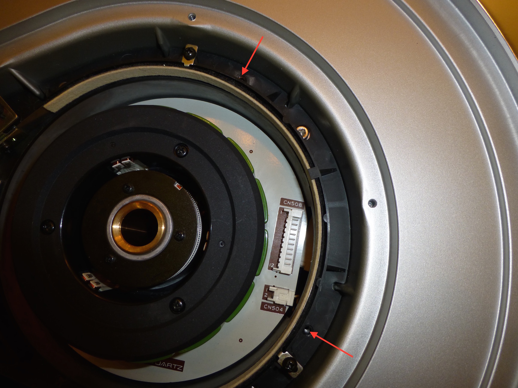
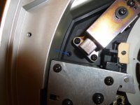
To remove the brake assembly, disconnect the cable by the lower left solenoid, and remove the screws notated below. The read arrows show machine screws, and the blue arrows show self-tapping screws. Note the self-tapping screw through the metal bracket is longer than the other.
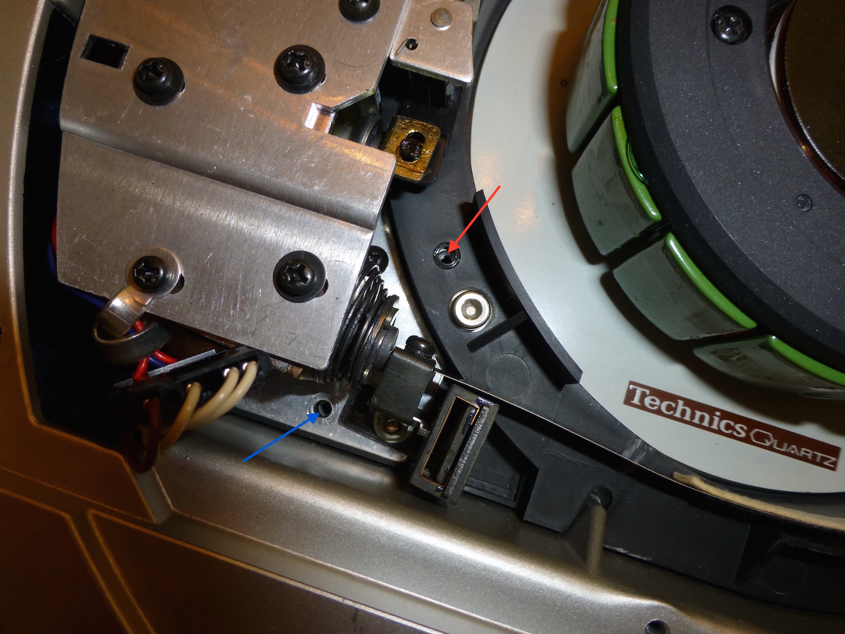
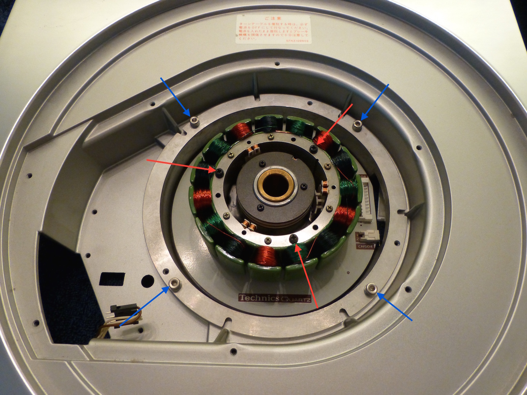
The entire brake assembly can then be lifted out. I removed the motor pan from the chassis, but you don't need to do this. The red arrows denote screws that need to be removed to pull the stator assembly, and the blue arrows are the four screws that attach the motor pan to the chassis. Be sure to unplug both cables to the PCB.

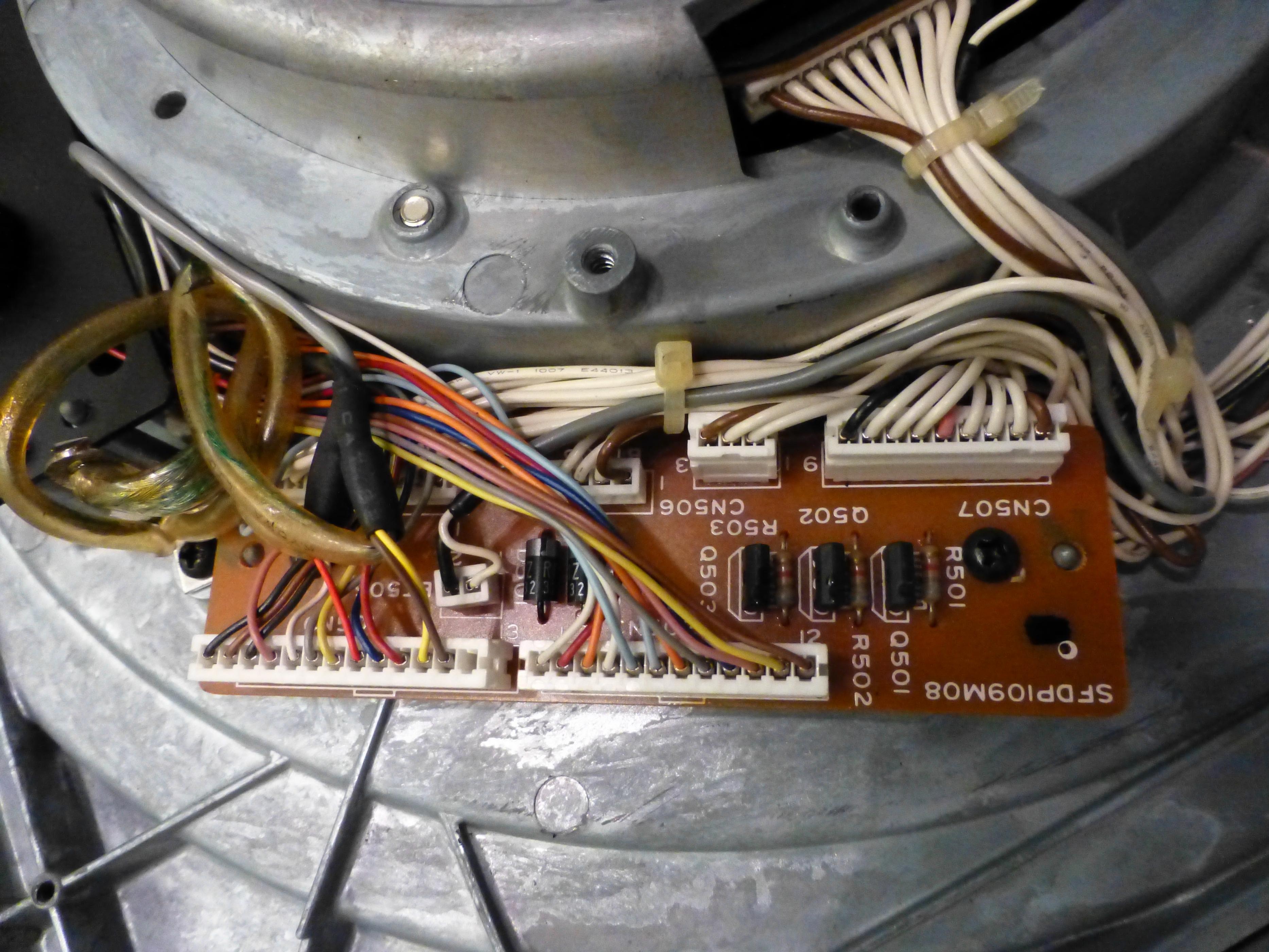
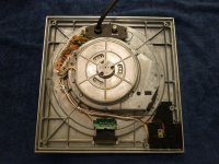
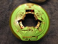
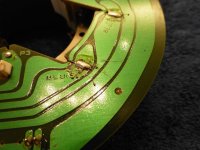
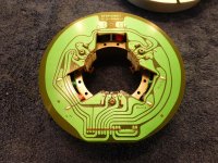
Next I cleaned the dust out of the pan, and washed most of the flux off the PCB, not getting too aggressive near the fine wires of the position detection coils. Note the solder splash.
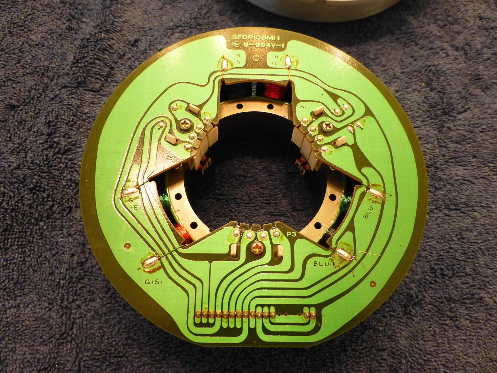

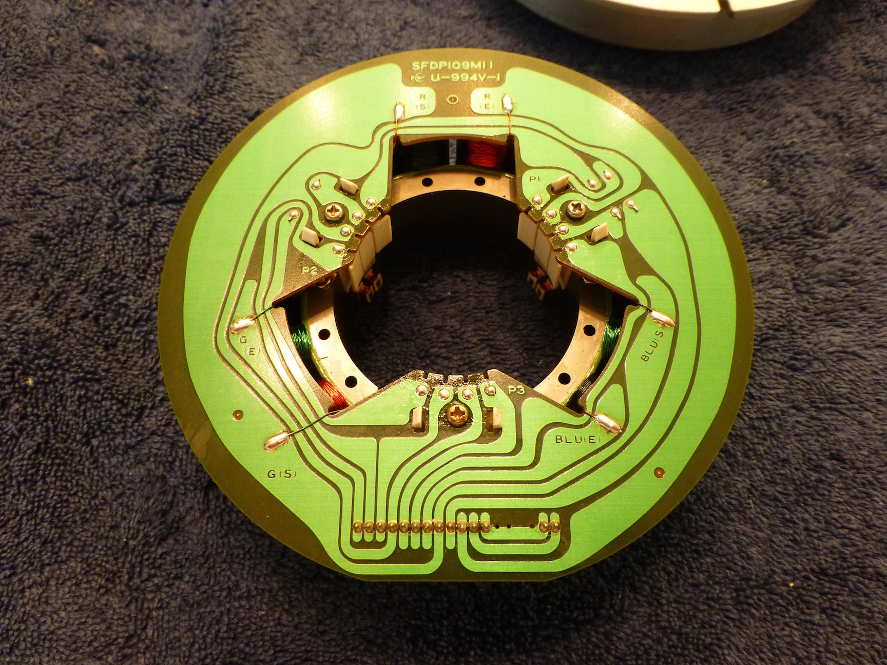
I didn't see any reason to take the bushing mount or servo coils out (you need to desolder them to remove them).
Simply follow the steps in reverse-order to put it back together.
To remove the brake assembly, disconnect the cable by the lower left solenoid, and remove the screws notated below. The read arrows show machine screws, and the blue arrows show self-tapping screws. Note the self-tapping screw through the metal bracket is longer than the other.
The entire brake assembly can then be lifted out. I removed the motor pan from the chassis, but you don't need to do this. The red arrows denote screws that need to be removed to pull the stator assembly, and the blue arrows are the four screws that attach the motor pan to the chassis. Be sure to unplug both cables to the PCB.
Next I cleaned the dust out of the pan, and washed most of the flux off the PCB, not getting too aggressive near the fine wires of the position detection coils. Note the solder splash.
I didn't see any reason to take the bushing mount or servo coils out (you need to desolder them to remove them).
Simply follow the steps in reverse-order to put it back together.
Attachments
-
 P1010537.jpg428.3 KB · Views: 1,227
 -
 P1010534.jpg453.8 KB · Views: 1,382
 -
 P1010535.jpg517.4 KB · Views: 1,377
 -
 P1010536.jpg487 KB · Views: 1,224
 -
 P1010526.jpg537.3 KB · Views: 1,358
 -
 P1010521.jpg545 KB · Views: 1,395
 -
 P1010523.jpg792.2 KB · Views: 1,226
 -
 P1010524.jpg503.2 KB · Views: 1,195
 -
 P1010525.jpg727.6 KB · Views: 1,211
 -
 P1010522.jpg547.8 KB · Views: 1,201
Last edited:
Click the image to get correct aspect ratio (why does it do that ?)
The forum software automatically resizes the images to a certain height, to keep the entire thread from becoming too tall, thereby saving you the arduous task of scrolling down a wee bit more to see the whole page...
- Home
- Source & Line
- Analogue Source
- The Incredible Technics SP-10 MK3 Thread