")
Screws, 13 out of 15 had pointed ends, two were blunt. Looks like all of yours are OK !
BTW, wasn't that me !
The screws that were ~1mm longer were proud by, yep, about ~1mm. I doubt it would've been enough to interfere with the platter, but I used the shorter screws in those two spots anyway.
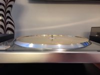
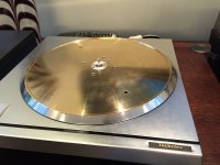
I'm waiting for one bi-polar cap to show up tomorrow that was listed incorrectly on the parts list, so I decided to polish the platter.
I used kitchen copper pot type cleaner for the copper, 0000 steel wool cleaned up the aluminum, and my 3" random-orbit polisher took care of making it all look pretty.


I used kitchen copper pot type cleaner for the copper, 0000 steel wool cleaned up the aluminum, and my 3" random-orbit polisher took care of making it all look pretty.
Attachments
Mk 3 on German eBay
Technics SP 10 Mk 3, *the holy grail* the best of all time DD, ultra rare | eBay
Hmmmmmmm for that price I would expect a warantte ! Is the plinth orgional ?
Dave
Technics SP 10 Mk 3, *the holy grail* the best of all time DD, ultra rare | eBay
Hmmmmmmm for that price I would expect a warantte ! Is the plinth orgional ?
Dave
Well, all good things must come to an end...
After the recap I was going through the checks and adjustments, and have ran in to rather significant issues. I don't believe this has anything to do with the recap, but sure speaks to checking everything out thoroughly before doing any work. I did a very fast check when the table arrived as I didn't want to run it with leaking caps. I ran it at 33 and checked the strobe to make sure everything looked okay, 45 went faster, and 78 went faster yet.
Upon putting it back together I adjusted the +/-32V supply voltages to spec, and verified the 12V and 5V supply voltages. All good.
The oscillator is running at 3.82µs vs. 3.8µs spec, so I left it alone.
The VS voltage was 1.7V while spec is 2.1V. Adjusting the VR had no influence on the measured voltage. I decided to move on down the list just in case something else was far out of spec and effecting other settings. RS current should be 0V with the table running at 33. Mine was -5V, and again adjusting the VR had no impact. Much later down the road I discovered that the motor will fight itself if VS or RS isn't in the right range, though they still measure the same and adjustments don't change the measurements.
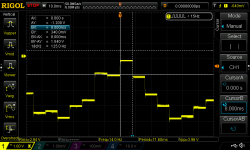
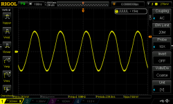
Synchronization was really interesting, pictured below. This is the only 'waveform' I could find.

Vcc for IC201, 202, and 203 measure correctly.
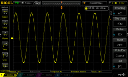
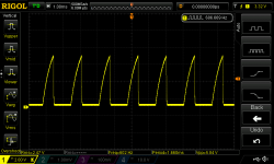
The FG signal at pin 16 of IC203 (AN660) looks good, though a tad low at 3.18Vpp/3.5Vpp. The frequency is also off by 0.1ms, which is a common thread throughout my measurements.

The oscillator at IC203 pin 2 (X1) looks okay though it's supposed to be 1.2Vpp according to the service manual. X2 voltage is low by approximately the same percentage.

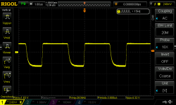
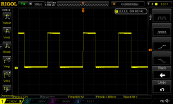
FO IC201 pin 6 doesn't look right - the negative cycles are too short.

FI at CN204 from the front panel doesn't look so good, though after Q201 at IC201 pin 7 it looks better except for what appears to be too short negative cycles.


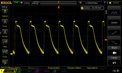
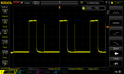
This is where things get really interesting. IC201 pin 9 should be a 20ms 4.2Vpp square wave, however it appears to be glitching every other cycle.

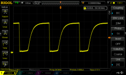
IC201 pin 15 and 16 should both be 20ms at 33rpm, but they're ~1.66ms. Also, the positive cycle of pin 16 (VS) appears too short.


Other things that stand out while measuring IC203:
1. Pin 3 stop/start voltage should be 6.0/5.0. Actual is 6.15/6.94.
2. Pin 4 should be 6.2/6.2. Actual is 6.25/6.99.
3. Pin 7 should be 8.2/6.7. Actual is 9.91/6.86.
4. Pin 8 should be 5.2/6.4. Actual is 3.65/5.90.
5. Pin 12 and 13 should be 2.6V while stopped but are 5.44. Running voltages are ok.
I'm open to everyone's thoughts on this one. To me, it looks like IC201 may be bad. IC203 is suspicious as well, but the glitching FS signal from IC201 could (I hope) be causing those issues.
.
After the recap I was going through the checks and adjustments, and have ran in to rather significant issues. I don't believe this has anything to do with the recap, but sure speaks to checking everything out thoroughly before doing any work. I did a very fast check when the table arrived as I didn't want to run it with leaking caps. I ran it at 33 and checked the strobe to make sure everything looked okay, 45 went faster, and 78 went faster yet.
Upon putting it back together I adjusted the +/-32V supply voltages to spec, and verified the 12V and 5V supply voltages. All good.
The oscillator is running at 3.82µs vs. 3.8µs spec, so I left it alone.
The VS voltage was 1.7V while spec is 2.1V. Adjusting the VR had no influence on the measured voltage. I decided to move on down the list just in case something else was far out of spec and effecting other settings. RS current should be 0V with the table running at 33. Mine was -5V, and again adjusting the VR had no impact. Much later down the road I discovered that the motor will fight itself if VS or RS isn't in the right range, though they still measure the same and adjustments don't change the measurements.
Synchronization was really interesting, pictured below. This is the only 'waveform' I could find.
Vcc for IC201, 202, and 203 measure correctly.
The FG signal at pin 16 of IC203 (AN660) looks good, though a tad low at 3.18Vpp/3.5Vpp. The frequency is also off by 0.1ms, which is a common thread throughout my measurements.
The oscillator at IC203 pin 2 (X1) looks okay though it's supposed to be 1.2Vpp according to the service manual. X2 voltage is low by approximately the same percentage.
FO IC201 pin 6 doesn't look right - the negative cycles are too short.
FI at CN204 from the front panel doesn't look so good, though after Q201 at IC201 pin 7 it looks better except for what appears to be too short negative cycles.
This is where things get really interesting. IC201 pin 9 should be a 20ms 4.2Vpp square wave, however it appears to be glitching every other cycle.
IC201 pin 15 and 16 should both be 20ms at 33rpm, but they're ~1.66ms. Also, the positive cycle of pin 16 (VS) appears too short.
Other things that stand out while measuring IC203:
1. Pin 3 stop/start voltage should be 6.0/5.0. Actual is 6.15/6.94.
2. Pin 4 should be 6.2/6.2. Actual is 6.25/6.99.
3. Pin 7 should be 8.2/6.7. Actual is 9.91/6.86.
4. Pin 8 should be 5.2/6.4. Actual is 3.65/5.90.
5. Pin 12 and 13 should be 2.6V while stopped but are 5.44. Running voltages are ok.
I'm open to everyone's thoughts on this one. To me, it looks like IC201 may be bad. IC203 is suspicious as well, but the glitching FS signal from IC201 could (I hope) be causing those issues.
.
Attachments
-
 DS1Z_QuickPrint22.png43.5 KB · Views: 915
 -
 DS1Z_QuickPrint19.png51.8 KB · Views: 907
 -
 DS1Z_QuickPrint12.png47 KB · Views: 905
 -
 DS1Z_QuickPrint13.png38.6 KB · Views: 906
 -
 DS1Z_QuickPrint20.png50 KB · Views: 896
 -
 DS1Z_QuickPrint4.png44.7 KB · Views: 923
 -
 DS1Z_QuickPrint7.png39.1 KB · Views: 899
 -
 DS1Z_QuickPrint8.png41 KB · Views: 901
 -
 DS1Z_QuickPrint10.png38.3 KB · Views: 899
The big question is, does it actually work ? Like it did before the re-cap ?
As documented here, my one has a fault that I believe I'm half way through. However my work load is way too high right now and I have outstanding customer orders so the MK3 has to wait.
What does CN206 look like ? And to help me later, are there any propriety plugs that fit into these measurement sockets ?
33 and 45 are correct according to the strobe, but there is a vibration in the chassis. 78 runs quite slow, surges, and you can feel the motor fighting itself.
The only testing I did before was a quick verification of functions. 33 showed good on the strobe, but I didn't verify 45 and 78 on the strobe. I didn't want to run it long due to the leaking caps. I hindsight I should have taken the chance.
What do you mean what does CN206 look like?
The only testing I did before was a quick verification of functions. 33 showed good on the strobe, but I didn't verify 45 and 78 on the strobe. I didn't want to run it long due to the leaking caps. I hindsight I should have taken the chance.
What do you mean what does CN206 look like?
Very interesting day.
From yesterday, most of the above actually looks okay with a couple of exceptions. IC201 (DN860) pin 9 is 19.8ms not counting that glitch, and both DN860s output the same waveform. I have to go back and check pin 15 and 16 now that I think I figured out how to set VS voltage. I also need to go back and check the various AN660 voltages.
As the MK2A is very similar so I spent a lot of time going through its schematics. The primary difference is that the MK3 uses two DN860s with the MN6042 in the middle. IC202 (DN860) generates the reference frequency and drives the strobe. The reference frequency is sent to MN6042 which is the variable pitch IC that drives IC201, the second DN860. IC201 and IC203 (AN660) circuit block are the same as the MK2A, except for the functions IC202 is doing.
The MK3 manual says to set VS voltage to 2.1V measuring between CN206 terminals 3 (+) and 1 (-), which are AN660 VO and VS. The MK2A manual says to measure between AO and VS, however I saw a reference on the block diagram for the MK2A that showed VS as 2.1 for 33, 2.8 for 45, and 4.8 for 78. If I measured VS referenced to 0V with the table running at 33 I was able to set it. The manual doesn't say to start the table, but at idle VS is a bit over 5V and doesn't have sufficient range.
For RS current the MK3 manual says to measure between CN206 5 (+) and 4 (-), which are 0V and AN660 ST2. The MK2A manual says to measure between AN660 AI and VO. Following the MK2A manual I was able to get 0V as specified with the table running at 33.
MK3 manual says to set sync position at CN206 2 (+) and 1 (-), but these are AN660 AI and VO - what's used to set RS current. Sync should be set with AN660 ST2 and 0V, which is confirmed by the MK2A manual, and what I did. It would seem they mixed up the pins for Sync and RS current. I've no idea about VS voltage as it appears both manuals may be wrong.
I set middle voltage per the manual with no issues. I'll tackle offset voltage tomorrow.
I'm not out of the woods yet though. When everything is cold the table runs fine, but after ~20 seconds I can feel vibrations from the motor, and they get progressively worse for a couple of minutes until it plateaus. Watching FG at AN660 pin 16, the waveform has steady phase and slightly modulating amplitude at first, but starts to shift in phase in concert with the motor vibrations. That'll be fun to track down.
Hi John
OK, if you move VR101 too far you blow the driver transistors, I blew two and have now replaced all 6 for consistency and matching. I used TIP41C and TIP42C. But then I got the same symptoms as you................................
Now I am driving the +/- 32V from bench PSU's current limited to 800mA with the interlinking connector/cable not fitted. Wire the bench PSU's directly into the driver PCB
You need to address page 9 of the manual 6th item. This is obtained from CN206 which is the unmarked white connector on the left of the middle PCB (control) Use the second pin from the left, maybe make a connector for it to ensure no shorting ?
Measure from the rising edge to the very slight notch in the sawtooth part, it's subtle, not like as shown. Do this for all speeds regardless and :
VR101 is VERY critical, if you can't get lock adjust it a bit and try again, never set it near fully clockwise unless you have a current limited power supply running it and a box of spare transistors !
You won't believe this will work, but careful adjustment of the PLL on VR203/204/205 whilst adjusting VR101 will stabilise it.
Now mine is working, I'll take a breather before attempting to do this scientifically rather than empirically.
Let us know if it works, and if you can do it properly without injecting the 40mV specified in item 8 page 9 ?
Dave
Last edited:
I believe I have everything on the control board dialed in correctly, except the brake which I haven't look at yet. Middle voltage has been set (VR102) and I was going to look at offset voltage today (VR101). Thanks for the tip on that one!
However, today the first time I fired it up FG was very erratic in phase and amplitude for 10 seconds or so, and then quieted right down and was rock solid - no vibrations in the table. I shut it off and will try it again later recording video of the scope screen.
My issues may be down to a cold solder joint or two. Certainly seems temp related.
- Home
- Source & Line
- Analogue Source
- The Incredible Technics SP-10 MK3 Thread