I don’t think my device adds mass. But it is not important. I also don’t think it is important how you call it damping or bias.
My tests show there is a fundamental misunderstanding about groove and stylus interaction for a linear tracking arm. This is important.
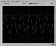
I did another test last night. Everything else was same as my 1st test except I use my diy ball bearing arm. The cartridge was Denon DL-103R, a low compliance cartridge. There was no damping device. Here is the results. Please see attached images. The distortions do exist in left channel only. It means that the needle was slammed onto right side of groove wall and lost contact with left side of groove wall.
The result is same as what I did on the air bearing arm. I believe that my tests are highly repeatable. Therefore, they are not tonearm specific. These tests raise questions which challenge fundamental thinking laying under linear tracking arm design.
The consensus for linear arm damping( or biasing) is that the stylus will be slammed either on left side or on right side. Therefore, damping should be applied on both sides with equal force. I thought the same until I did the tests.
However, my tests show otherwise. A stylus of linear arm will be slammed on right side of groove wall only. So, if the damping applies equal force on both sides, it won’t correct the problem. The stylus isn’t still centered in groove. This is why I said all the damping devices for linear arms on the market are not correctly implemented.
I would like to see someone else do the same test.
My tests show there is a fundamental misunderstanding about groove and stylus interaction for a linear tracking arm. This is important.
I did another test last night. Everything else was same as my 1st test except I use my diy ball bearing arm. The cartridge was Denon DL-103R, a low compliance cartridge. There was no damping device. Here is the results. Please see attached images. The distortions do exist in left channel only. It means that the needle was slammed onto right side of groove wall and lost contact with left side of groove wall.
The result is same as what I did on the air bearing arm. I believe that my tests are highly repeatable. Therefore, they are not tonearm specific. These tests raise questions which challenge fundamental thinking laying under linear tracking arm design.
The consensus for linear arm damping( or biasing) is that the stylus will be slammed either on left side or on right side. Therefore, damping should be applied on both sides with equal force. I thought the same until I did the tests.
However, my tests show otherwise. A stylus of linear arm will be slammed on right side of groove wall only. So, if the damping applies equal force on both sides, it won’t correct the problem. The stylus isn’t still centered in groove. This is why I said all the damping devices for linear arms on the market are not correctly implemented.
I would like to see someone else do the same test.
Attachments
Hi Super.
Very interesting results. It puts me in mind of the clearaudio arms. As these are mechanical, like your ball race arm, damping is supplied by the mechanical contact between race and tube. Clearaudio recommend that the rail is set very slightly downhill towards the spindle. This would supply a bias similar to that which you have implemented in you air bearing arm. It would appear that they have come to the same conclusion as you. Could you repeat the test on your ball race arm with the rail sloped and see if this has a positive effect. It would cause the VTA to change slightly as the arm traversed the record but if the benefits outweigh the negatives it would be worth implementing.
Niffy
Your tests look more like lack of tracking weight, or dynamic mispositioning of sled is causing over deviation of cantilever positioning which is causing dynamic mistracking.
It seems that passive linear tracking is flawed due to too high sled/arm/cartridge masses, especially for eccentric discs.
Lowering moving masses will serve to raise system resonance frequencies up into audio band.
Sled damping needs to be velocity dependent, and not frictional.
Dan.
It seems that passive linear tracking is flawed due to too high sled/arm/cartridge masses, especially for eccentric discs.
Lowering moving masses will serve to raise system resonance frequencies up into audio band.
Sled damping needs to be velocity dependent, and not frictional.
Dan.
It seems that passive linear tracking is flawed due to too high sled/arm/cartridge masses, especially for eccentric discs.
I would disagree with this statement. I calculated the cantilever displacement purely due to carriage mass eg bearing friction, arm wires resistance etc not included. I based the calculation on my arm and cartridge with a record with a 0.5mm eccentricity which will cause the stylus to dance back and forth by 1mm, quite a severe case.
Carriage mass. 50g
compliance. 20um/mN
cantilever length 5mm
speed. 33.3rpm
This case would result in the cantilever being displaced by only 0.02 degrees. Well within the zone where the cartridge is still linear, in fact a lot less than the deflection observed due to groove modulation. With this arm /cartridge combination the cantilever resonance is just under 5hz safely above the 0.55hz driving force caused by disc eccentricity.
Passive linear tracking is not flawed and any short comings it may have are massively outweighed by the advantage of being able to utilize very short armtubes.
Niffy
Hi Niff
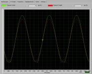
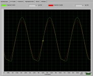
I did the test as you requested last night. I tilted the ball bearing arm less than 1 degree and adjusted azimuth to make sure the stylus is perpendicular to the record. Here is the result. Please see the image.
For air bearing arm, the distortion from left channel starts at about 7 db signal because frictionless bearing. Air bearing doesn’t have any damping. But for ball bearing arm, the bearing and glass rail are not frictionless. The distortion starts at 10 db. This friction acts as damping for the arm. If I tilt the arm more, the distortion will switch to right channel. It means overdamping(or basing). The stylus hits the left side of groove wall.
So, for an air bearing arm, damping is a must, but for ball bearing arm, you may get away without damping. However, you must realize that the ball bearing may have high friction since damping is not necessary.
Attachments
Hi Super.
Thanks for the test. The sub1 degree tilt has certainly improved the plots.
The result would suggest that the force required to track from outer to inner groove is significant even with a virtually frictionless bearing. This seems a bit counterintuitive especially as the distortion always appears in the left channel suggesting that this force is more significant than that due to eccentricity.
I Have the begining of a theory as to why this may be but will have to think on it a bit more before committing it to paper.
Niffy
Your tests look more like lack of tracking weight, or dynamic mispositioning of sled is causing over deviation of cantilever positioning which is causing dynamic mistracking.
It seems that passive linear tracking is flawed due to too high sled/arm/cartridge masses, especially for eccentric discs.
Lowering moving masses will serve to raise system resonance frequencies up into audio band.
Sled damping needs to be velocity dependent, and not frictional.
Dan.
I don’t think the stylus lacks tracking weight because the right channel is almost perfectly tracked. VTF was correct. It isn’t caused by moving mass either. The cause is the interaction between groove wall and stylus. I can do another test to approve my point. But I need to change the cartridge to a cheap one. I will run the cartridge on a grooveless disk. I expect that the cartridge will be stationary and will not move sideways.
A cheap ink jet printer can do 600 dpi or 1200 dpi. The resolution is well enough for tracking records, but the tracking system may be very difficult to implement for diyers. I am sure active tracking arm will have some kind of problems too.
I don’t think the linear tracking arm’s mechanism is flawed, but little complicated.
Hi Super.
Thanks for the test. The sub1 degree tilt has certainly improved the plots.
The result would suggest that the force required to track from outer to inner groove is significant even with a virtually frictionless bearing. This seems a bit counterintuitive especially as the distortion always appears in the left channel suggesting that this force is more significant than that due to eccentricity.
I Have the begining of a theory as to why this may be but will have to think on it a bit more before committing it to paper.
Niffy
Tilting the arm means adding damping force(biasing) on left side of groove wall. Therefore, the distortion on left channel is gone. For right channel, the stylus is being slammed on the right side of groove wall. Extra damping is not necessary.
Last edited:
I think the bias applied buy the tilt is more significant than any additional damping effect.
Little grey cells engaged and working the problem.
Niffy
I don’t think so. On a ball bearing arm, you may tilt the arm because the distortion starts at about 10 db. It means ball bearing arm is ok without additional damping for wide range of dynamics. But the degree of tilting is limited. And, you may tilt the arm only if the friction exists. For air bearing, it is frictionless. Its distortion starts at about 6 db. It means that it has narrow coverage of dynamic range without additional damping. And, the distortion is much more serious than ball bearing arm without additional damping. However, it doesn’t mean ball bearing is superior over air bearing. Air bearing is the best mechanism for linear tracking arm for many reasons( we are not talking about active tracking here).
Last edited:
Super,
So a mechanical arm has built in damping, and an air bearing needs added damping. So a decent mechanical bearing arm is almost something for nothing but simpler?. I know this is too cut and dry, but I do know that the mechanical grounding and damping does have a simple superiority over air bearing. Maybe I'm lost here, but it appears that my assessment of a little bit of controlled friction is a good thing?. None the less I'm following this arm with much interest") .
.
Colin
So a mechanical arm has built in damping, and an air bearing needs added damping. So a decent mechanical bearing arm is almost something for nothing but simpler?. I know this is too cut and dry, but I do know that the mechanical grounding and damping does have a simple superiority over air bearing. Maybe I'm lost here, but it appears that my assessment of a little bit of controlled friction is a good thing?. None the less I'm following this arm with much interest
.Colin
Hi Super.
I've had a think about the test results you've posted.
With the air bearing arm the total lateral friction is due to the residual friction of the air bearing (negligible), the stiffness of the arm wires, the stiffness of the air tube, the friction of the grooved bearings and the stiffness of the damping thread. This needed a 0.7g bias force to balance it.
With the ball race arm the total lateral friction is due to the friction of the ball race bearings and the stiffness of the arm wires. If I remember correctly your ball race arm weighed 35g. You found that a rail slope of less than 1 degree biased the friction. A 0.8 degrees slope would give a bias force of 0.5g.
This would show that the total lateral friction of the air bearing arm is actually higher than for the ball race arm, an unexpected conclusion. I am not suggesting that this implies that one system is better than the other. This would also explain why unbiased distortion was higher with the air bearing.
Did you perform the same test With the air arm before you fitted the damping system. If I am correct I would expect that, due to lower total friction, the distortion would be lower also.
What you have shown is that biasing the arm so that loading of the stylus is symmetrical is important. Thanks for this valuable insight.
A question I failed to ask concerns your test record. How well centered is this record? If it is perfectly centered there would be no wobble, and no loading to the right, which would explain why distortion only occurred in the left channel.
Niffy
I did a little test and measured the the actual force required to overcome the lateral friction of my arm. The left and right measurements showed good balance both being about 3mN (0.3g). When playing a perfectly centered record the right side of the stylus would see a constantly force that would deflect the cantilever by about 0.06mm to the left causing an LTA error of 0.7degrees. If I biased this, by tilting the rail by a bit less than half a degree, the forces should balance and true tangential tracking be achieved. (I would have to conically dish the platter at the same angle to maintain azimuth and VTA).
The problems with this approach rears its head if the record is eccentric. Eccentricities with a peek to peek amplitude of less than 0.1mm probably won't move the carriage at all. On more severe eccentricities the cantilever would displace to 0.7degrees before the carriage started to move In that direction. With bias added the carriage would move easily to the left but would have to overcome both friction and bias (2x3mN) to move to the right causing much higher LTA error.
This does not include the effect of the pitch of the groove . Perhaps the ideal balance might be a smaller bias say 1.5mN. Or better yet a mechanism to centered discs.
Niffy
Niffy,
I noticed this aspect too, with a bias all is mostly good if the disc is perfectly centered, but extreme rare to find this. The best that can be done is minimal friction bearings, ultra flexible non intrusive wiring and well placed geometrics. I had found that the placement of weight also had a huge role.
Colin
I noticed this aspect too, with a bias all is mostly good if the disc is perfectly centered, but extreme rare to find this. The best that can be done is minimal friction bearings, ultra flexible non intrusive wiring and well placed geometrics. I had found that the placement of weight also had a huge role
. Colin
Hi Super.
I've had a think about the test results you've posted.
With the air bearing arm the total lateral friction is due to the residual friction of the air bearing (negligible), the stiffness of the arm wires, the stiffness of the air tube, the friction of the grooved bearings and the stiffness of the damping thread. This needed a 0.7g bias force to balance it.
With the ball race arm the total lateral friction is due to the friction of the ball race bearings and the stiffness of the arm wires. If I remember correctly your ball race arm weighed 35g. You found that a rail slope of less than 1 degree biased the friction. A 0.8 degrees slope would give a bias force of 0.5g.
This would show that the total lateral friction of the air bearing arm is actually higher than for the ball race arm, an unexpected conclusion. I am not suggesting that this implies that one system is better than the other. This would also explain why unbiased distortion was higher with the air bearing.
Did you perform the same test With the air arm before you fitted the damping system. If I am correct I would expect that, due to lower total friction, the distortion would be lower also.
What you have shown is that biasing the arm so that loading of the stylus is symmetrical is important. Thanks for this valuable insight.
A question I failed to ask concerns your test record. How well centered is this record? If it is perfectly centered there would be no wobble, and no loading to the right, which would explain why distortion only occurred in the left channel.
Niffy
I think your calculation is incorrect. The correct formula should be
F(total)=F1(bearing)+F2(added force)
Where, F1(bearing)=F(m1, u1), F2(added force)=F(m2, u2)
M is arm moving mass and u is coefficient of friction.
therefore,
F(total)=F1(m1, u1)+F2(m2, u2)
In other words, the friction force of a bearing is a function of m, mass and u, coefficient of friction. For ball bearing, mass is very critical since adding mass will have great effect on friction. Where F1 can be a large value. For air bearing, adding mass will not have too much effect on friction because air bearing coefficient of friction is almost zero when the bearing travels at such low speed. F1 for air bearing can be a very low value. The phenomenon of tail wagging the dog happens just because very lower value of F1. So, F(total) for air bearing can be smaller than F(total) for ball bearing even if added force for air bearing is greater than added force for balling bearing .
However, the level of friction force of a linear arm is NOT the only factor to judge how good the arm is. The key is controllable force of friction. Ball bearing arm has a constant force of friction. Its friction can not be reduced. For air bearing, the force of friction can be optimized to fit wide range of cartridges.
I can’t tell if the test lp is eccentric. I can only see there is very very tiny side movements just as when a normal lp is playing.
Hi Super.
I did put the word negligible in brackets next to air bearing for exactly that reason. I was suggesting that the resistance to movement (friction ) due to the air tube and damping mechanism was as great or greater than that due to the races in the ball race version, as both have arm cables that term would cancel. The resistance to movement of the air tube and arm wires is due to their stiffness not their masses so coefficients of friction are not applicable here.
Niffy
Last edited:
Hi Super.
I did put the word negligible in brackets next to air bearing for exactly that reason. I was suggesting that the resistance to movement (friction ) due to the air tube and damping mechanism was as great or greater than that due to the races in the ball race version, as both have arm cables that term would cancel. The resistance to movement of the air tube and arm wires is due to their stiffness not their masses so coefficients of friction are not applicable here.
Niffy
I did put the word negligible in brackets next to air bearing for exactly that reason. I was suggesting that the resistance to movement (friction ) due to the air tube and damping mechanism was as great or greater than that due to the races in the ball race version, as both have arm cables that term would cancel. The resistance to movement of the air tube and arm wires is due to their stiffness not their masses so coefficients of friction are not applicable here.
Niffy
Sorry about the double post, had a glitch.
I agree friction only play a role, it doesn't direct the show. Rigidity and damping are more significant in my books. Your new arm and findings are fascinating and have inspired me to investigate and question.
The very very small movement is the eccentricity I would have expected and would cause a small LTA error with my arm. It's how to reduce this to negligible amounts that I am investigating.
Niffy
I did a little test and measured the the actual force required to overcome the lateral friction of my arm. The left and right measurements showed good balance both being about 3mN (0.3g). When playing a perfectly centered record the right side of the stylus would see a constantly force that would deflect the cantilever by about 0.06mm to the left causing an LTA error of 0.7degrees. If I biased this, by tilting the rail by a bit less than half a degree, the forces should balance and true tangential tracking be achieved. (I would have to conically dish the platter at the same angle to maintain azimuth and VTA).
I am not sure if I understand this part correctly.
While the arm is not playing, the resistances on both sides are same, i.e. 0.3 g. Yes. I understand this. But once the arm is playing on a concentric disk, there is a force to slam the stylus onto left side. In other words, the distortion should be on the RIGHT side. So, if you tilted the arm down, the distortion should be even larger. If you tilted the arm up, you may balance the force. I am not sure if I understand it correctly.
The problems with this approach rears its head if the record is eccentric. Eccentricities with a peek to peek amplitude of less than 0.1mm probably won't move the carriage at all. On more severe eccentricities the cantilever would displace to 0.7degrees before the carriage started to move In that direction. With bias added the carriage would move easily to the left but would have to overcome both friction and bias (2x3mN) to move to the right causing much higher LTA error.
This does not include the effect of the pitch of the groove . Perhaps the ideal balance might be a smaller bias say 1.5mN. Or better yet a mechanism to centered discs.
In the first part, the test was done on a concentric disk. How does the eccentricity displace the stylus?
- Home
- Source & Line
- Analogue Source
- DIY Air Bearing Linear Arm