I bought the New Way air bearing from here
https://www.motionusa.com/online/shop/new-way-air-bearings/air-bushings
They sell shaft for $9.00 per 25 mm. I bought mine from
MetalsDepot® - T303 Stainless Steel TGP Shafting
The diameter tolerance is +/- .0005". New Wary 's requirement is +/- .0002-.0007". It is much cheaper. Then, I used 2000 grit sand paper and put the shaft on a drill press to sand it to mirror shine.
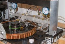
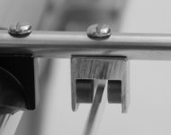
I added my damping device today. I have a pair of u-groove ball bearings in hand so they are prefect for the job. The string is polyester thread. It can be stretched a little. I moved the device from back side to front because it is more effect on the front and it is easy for me to install the device. I made two small buckets as weights. The buckets weight 1.7 gram alone. If I want to increase the weight, I can add lead shot pellets. Each pellet is 0.1 gram. If I want to damp different low frequency, I may attach a piece of rubble band with the thread to make it more stretchable and combine with different weights. But I don't see the reasons to do this so far. The cartridge I used was Dynavector 17D3. It is high compliance and recommended VTF is 1.8-2.0 g.
Before I installed the damping device, I had the 17D3 on the arm. I was wondering why the sound was kind of dull and boring. The high frequency didn't sound right. 17D3 never lacks micro dynamics but is some what weak in bass. After I installed the damping device, it really opened the sound. High frequency was really wonderful and natural. The sound came to life. The bass was very well defined. The damping weight I used for 17D3 was 1.8 gram. In the meantimes, I also increased air pressure to 42 psi to make the arm stiffer.
I think my damping device is better than silicone oil damping device.
1. Silicone oil is messy. Mine is complete dry device.
2. Silicone oil damping is non-directional. Mine is directional. I really don't see the needs for damping all directions except the direction which is parallel to the bearing shaft.
3. It is hard to guess how much damping force you apply with silicone oil. Mine is very straight forward by the weight.
On my air bearing arm, it may not be necessary to use damping device for some of cartridges. It may be ideal still to add light damping to reduce distortion and noise. I will try different high compliance cartridges later on.
Attachments
O
Hi Super,
The Dynavector 17d3 would fall in the Medium compliance at 15, most MC carts don't ever get out of the medium territory. I'd be curious to see how a true higher compliance cart such as the Shure M97 would fare, the cantilever is far more elastic so would be affected by mass. None the less it is a nice project my friend, I would get my hands a little more wet but the $195 for the linear air bearing is a bit much right now :/.
How do you find the sound compared to a mechanical arm?, do the gains outweigh the added complexity?
Colin
Hi Colin,
Actually, I am not satisfied with any ball bearing designs. This is why I made my air bearing arm. I don't like two glass tubings and one ball bearing design because it is not a safe design. The carriage can very easily drop off the glass rails and damage cartridge. It happened to me. Luckily, the cartridge was fine. Its friction is simply too high. In reality, once the bearing is not centered, its friction on one side can get too low while it actually requires higher. And on another side, the friction can get too high while it needs lower friction. It has shortcoming of Cantus's design, various VTF, too.
I don't like Clear audio's approach because the arm pivot is not stiff enough. It can move forwards and backwards. I also don't like Cantus style, that is what I have now. Cantus style ball bearing design has stiffer pivot but still not enough. It has different force of damping on two side of ball bearing so its VTF varies. Of course, both Cantus' and Clear Audio's are very safe for cartridges. All the ball bearing designs require low compliance cartridge to work best. I have my own idea about ball bearing design. I think it is better than all the designs I mentioned above, but I have to actually do it to approve if it works better than other designs. And I don't think I will do it because I think air bearing is the best solution for linear tracking arm.
Comparing air bearing, ball bearing designs have one advantage. Ball bearing designs are mechanically grounded, while air bearing depends on arm and bearing to absorb resonance. Anyway, ball bearing arm can still sound very good under the right combination. I believe that for arm design, there are nothing absolute and everything are relative. Everything are about optimal in relation to other factors.
Air bearing arm's trackability is superior to any other means for linear tracking arm. With a damping mechanism in place, air bearing works very good with wide range of cartridges. Its sound is so well defined. I asked myself why we need a pivot arm. My air bearing arm is much quiet than ball bearing and has much less distortions. I thought about magnetic leviation linear arm, but it was just a thought. If it works, it can be comparable with air bearing arm and can even be better because it doesn't need an air compressor.
I don't make things complicated if I don't need to. But one thing for sure, I won't make any arm in its full length. Linear tracking arm must be short to work best. A short arm makes things a little complicated because you need a retractable mechanism. If a short arm makes things complicated, I would certainly say it is worth to do.
I also can't stand rough finish. My most advanced tools are a band saw and a drill press. Otherwise, I may make the arm even nicer both looking and functionality. Roughness doesn't mean simplicity.
Last edited:
Hi Super,
I think in the elegant simplicity department we North Americans couldn't even nip the heels of the Europeans in that department, many American things are profoundly overtly engineered in the bigger is better philosophy, but there are exceptions, Apple being one.
The air bearing makes sense, though as you point out it's now entirely up to the arm to dissipate internal resonances vs the mechanical ground of the bearings. I'm not bashing your design which is very similar to the ESP linear arm, just looking for the info to justify the cost") . Speaking of mag lev, that's what I've been working on lately, it's although a lot more complex from a stability standpoint :/.
. Speaking of mag lev, that's what I've been working on lately, it's although a lot more complex from a stability standpoint :/.
Colin
I think in the elegant simplicity department we North Americans couldn't even nip the heels of the Europeans in that department, many American things are profoundly overtly engineered in the bigger is better philosophy, but there are exceptions, Apple being one.
The air bearing makes sense, though as you point out it's now entirely up to the arm to dissipate internal resonances vs the mechanical ground of the bearings. I'm not bashing your design which is very similar to the ESP linear arm, just looking for the info to justify the cost
. Speaking of mag lev, that's what I've been working on lately, it's although a lot more complex from a stability standpoint :/.Colin
Update:
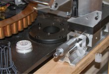
I am using 1/16” latex tubing to feed the 40 psi air to the bearing. But I am always afraid that the latex tubing can’t resist high air pressure because I destroyed one with 50 something psi air pressure. I just bought 1/16” Tygon ND100-65 medical plastic tubing from Amazon. The tubing is almost as flexible as latex and its working pressure is 55 psi. It should have no problem since I even added some damping. A little resistance from the tubing should be beneficial.
I will rise the air pressure to 50-55 psi. The bearing will get stiffer. I also will rise the compressor output air pressure to 90 psi. My compressor runs highest pressure 80 psi with temperature at 105 F so far. Therefore, I can run the compressor even higher pressure. It is time to put high pressure on. I highly recommend Tygon tubing.
I am using 1/16” latex tubing to feed the 40 psi air to the bearing. But I am always afraid that the latex tubing can’t resist high air pressure because I destroyed one with 50 something psi air pressure. I just bought 1/16” Tygon ND100-65 medical plastic tubing from Amazon. The tubing is almost as flexible as latex and its working pressure is 55 psi. It should have no problem since I even added some damping. A little resistance from the tubing should be beneficial.
I will rise the air pressure to 50-55 psi. The bearing will get stiffer. I also will rise the compressor output air pressure to 90 psi. My compressor runs highest pressure 80 psi with temperature at 105 F so far. Therefore, I can run the compressor even higher pressure. It is time to put high pressure on.
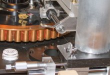
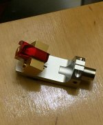
I highly recommend Tygon tubing.I recently bought an Audio-Technica AT-LH18/0CC Headshell and modified it to fit my arm. AT-LH18 is made of special aerospace aluminum. It is hard. I also made an option so I can change different headshell in the future if I want to. It is easy to install certain kinds of cartridges now because I can take the headshell off the arm and install the cartridge first. The headshell is also ¼ shorter than previous one. I usually don’t like wood headshell because I think wooden headshell sounds slow and sloppy. I prefer fast and natural sounding. However, the aluminum body of 17D3 combined with AT-LH18 sounded too fast and edgy for me. In order to slow it down, I added a 2mm thick carbon fiber. It is the right combination for my taste now.
I am also experimenting eddy current damping now. Thanks for your input, Clavin! I looked Dennesen arm. First, I am not sure if their damping force is enough. 2ndly, damping force is not adjustab. For eddy current damping, I need to find a good balance between moving mass, adjustability and complexity. But for now, I can’t find any better options than my damping device. It is simple, practical and user fully controllable. I proposely add 0.1 g more on the left side bucket so it will have slight heavier inward pulling force. I can tell the cartridge is running very smooth now.
I am also experimenting eddy current damping now. Thanks for your input, Clavin! I looked Dennesen arm. First, I am not sure if their damping force is enough. 2ndly, damping force is not adjustab. For eddy current damping, I need to find a good balance between moving mass, adjustability and complexity. But for now, I can’t find any better options than my damping device. It is simple, practical and user fully controllable. I proposely add 0.1 g more on the left side bucket so it will have slight heavier inward pulling force. I can tell the cartridge is running very smooth now.
Attachments
Last edited:

Ok, I just had a closer look at your photos and noticed this one.
Back when I was an apprentice, I made an eddy current clutch for a coil winder machine.
The form was quite similar to the diagram shown below, except both sides were aluminium discs, the driving side mounted with 6 magnets, and the driven disc was cut radially so as to form 6 segments.
The cuts went close to the centre, but not all the way.
The theory as explained to me at the time was that some electrical resistance in the driven disc is necessary for more ideal operation, and the radial cuts alter the induced current paths causing higher electrical resistance.

Perhaps your rectangular section damping rail would benefit by vertical cuts, making vertical fingers akin to a hair comb.
Dan.
View attachment 464382
Ok, I just had a closer look at your photos and noticed this one.
Back when I was an apprentice, I made an eddy current clutch for a coil winder machine.
The form was quite similar to the diagram shown below, except both sides were aluminium discs, the driving side mounted with 6 magnets, and the driven disc was cut radially so as to form 6 segments.
The cuts went close to the centre, but not all the way.
The theory as explained to me at the time was that some electrical resistance in the driven disc is necessary for more ideal operation, and the radial cuts alter the induced current paths causing higher electrical resistance.
View attachment 464383
Perhaps your rectangular section damping rail would benefit by vertical cuts, making vertical fingers akin to a hair comb.
Dan.
Dan,
You must know about eddy current more than I do. Anyway, I found something new today. What I found means that eddy current is not a correct method to damp. Please read my next post. The picture you used is not mine. It is Dennesen arm.
In my previous post, I quoted Michael Fremer's comment. He said:
The grooves of most LPs are not concentric because of pressing inconsistencies, which means the groove is constantly shifting the tonearm's mass back and forth. Because the stylus is at the end of a spring mechanism (the cantilever's suspension), if you use a cartridge with too high a compliance—too floppy a spring—you can have the tail wagging the dog, in that the motion of the groove spiral will move the cantilever from its central position. The risk is then that with a frictionless bearing the stylus might be slammed from one groove wall to the other.
His comment made me thinking. If the stylus is slammed from one groove wall to the other due to eccentric disk , what happens for a concentric disk? Is the stylus still centered or almost centered in the groove for a linear tracking arm?
To approve my point, I did a test today. Before I explain the test I did, I would like explain how my damping device works so everyone can understand my reasoning.
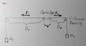
Please see Fig 1. In Fig 1, the pulling force F1 equals F2. The weights, W1 and W2, are same although the distance D1 and D2 are different. When the cartridge travels, the distance D1 and D2 change but the pulling force, F1 and F2 don’t change. Therefore, it damps unwanted lateral movements.
I used 1st track of side 2 of The Ultimate Analogue Test LP to do the test. This track is for adjusting anti-skating on a pivot arm. You may either listen or view the signal on an oscilloscope. If you hear buzz noise or see the distortion on an oscilloscope, it means anti-skating is not enough or too much. In other words, the stylus is not centered in groove because skating force. Usually, it is very hard to completely get rid of distortion at 12 db on a pivot arm.
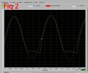
I played this track on my air bearing linear tracking arm. I assumed that both channel should be same and no distortion exists because linear arm has no skating force. According Fremer, the distortion should move from one channel to another if the disk is eccentric. But for concentric disk, there should be no distortion at all because the force is equal for both groove walls and the stylus should be centered. Now let’s see the test result. Please see Fig 2.
In Fig 2, green line is left channel and red line is right channel. The distortion does exist in left channel even for a concentric disk(Test LP) under equal damping force for both channels. Is the distortion caused by skating force on a linear arm? I am not going to discuss this here. This is not my purpose here.
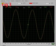
Then, I added more weight on the left side(left channel) of my damping device until the distortion disappeared. Please see Fig 3. The weight on left side is .7 g heavier than right side.
From this test, I can draw following conclusions.
1. Fremer is not correct. The stylus is always being slammed on the right side of groove wall for a concentric disk. On a eccentric disk, it may be still always slammed on the right side of groove wall.
2. Applying equal damping force is not correct damping method. The linear tracking arms on the market have either no damping or incorrect damping method.
3. My damping device is the only device which has correct damping method and adequate damping to keep the stylus centered in groove.
4. Both silicone oil damping and eddy current damping are not correct damping methods because they apply equal force on both sides laterally.
On my arm, I still keep right side damping force 1.6 g(the weight of small bucket) and left side 2.3 g just in order to keep it stable. In fact, it may be possible just to damp left side just as an anti-skating device on a pivot arm.
The grooves of most LPs are not concentric because of pressing inconsistencies, which means the groove is constantly shifting the tonearm's mass back and forth. Because the stylus is at the end of a spring mechanism (the cantilever's suspension), if you use a cartridge with too high a compliance—too floppy a spring—you can have the tail wagging the dog, in that the motion of the groove spiral will move the cantilever from its central position. The risk is then that with a frictionless bearing the stylus might be slammed from one groove wall to the other.
His comment made me thinking. If the stylus is slammed from one groove wall to the other due to eccentric disk , what happens for a concentric disk? Is the stylus still centered or almost centered in the groove for a linear tracking arm?
To approve my point, I did a test today. Before I explain the test I did, I would like explain how my damping device works so everyone can understand my reasoning.
Please see Fig 1. In Fig 1, the pulling force F1 equals F2. The weights, W1 and W2, are same although the distance D1 and D2 are different. When the cartridge travels, the distance D1 and D2 change but the pulling force, F1 and F2 don’t change. Therefore, it damps unwanted lateral movements.
I used 1st track of side 2 of The Ultimate Analogue Test LP to do the test. This track is for adjusting anti-skating on a pivot arm. You may either listen or view the signal on an oscilloscope. If you hear buzz noise or see the distortion on an oscilloscope, it means anti-skating is not enough or too much. In other words, the stylus is not centered in groove because skating force. Usually, it is very hard to completely get rid of distortion at 12 db on a pivot arm.
I played this track on my air bearing linear tracking arm. I assumed that both channel should be same and no distortion exists because linear arm has no skating force. According Fremer, the distortion should move from one channel to another if the disk is eccentric. But for concentric disk, there should be no distortion at all because the force is equal for both groove walls and the stylus should be centered. Now let’s see the test result. Please see Fig 2.
In Fig 2, green line is left channel and red line is right channel. The distortion does exist in left channel even for a concentric disk(Test LP) under equal damping force for both channels. Is the distortion caused by skating force on a linear arm? I am not going to discuss this here. This is not my purpose here.
Then, I added more weight on the left side(left channel) of my damping device until the distortion disappeared. Please see Fig 3. The weight on left side is .7 g heavier than right side.
From this test, I can draw following conclusions.
1. Fremer is not correct. The stylus is always being slammed on the right side of groove wall for a concentric disk. On a eccentric disk, it may be still always slammed on the right side of groove wall.
2. Applying equal damping force is not correct damping method. The linear tracking arms on the market have either no damping or incorrect damping method.
3. My damping device is the only device which has correct damping method and adequate damping to keep the stylus centered in groove.
4. Both silicone oil damping and eddy current damping are not correct damping methods because they apply equal force on both sides laterally.
On my arm, I still keep right side damping force 1.6 g(the weight of small bucket) and left side 2.3 g just in order to keep it stable. In fact, it may be possible just to damp left side just as an anti-skating device on a pivot arm.
Attachments
Last edited:
The issue is keeping the cantilever cantered in the cartridge magnetic circuit. This is why very high compliances are not suitable. Overly high compliance allows sled overshoot and lateral resonance causing too much lateral deviation of the cantilever...the tail wagging the dog condition.
Dan.
Dan.
My test shows the tail only wags the dog to right side.
Equal force damping may reduce inertia of bearing(It still needs to be approved), but it can’t keep the stylus centered in groove. Equal force damping means no damping at all. Kuzma’s damping device is not correctly implemented. So are the others.
Equal force damping may reduce inertia of bearing(It still needs to be approved), but it can’t keep the stylus centered in groove. Equal force damping means no damping at all. Kuzma’s damping device is not correctly implemented. So are the others.
If I am not mistaken, damping will result from the friction in the axles of the pulleys and the friction associated with the string running in those pulleys. If it were not for that friction, the mechanism I see would only add to the lateral mass of the arm excepting that it is applied at some distance ahead of the linear bearing, forming a moment about that point and a consequent increase in the vibrational complexity of the assembly. It is interesting that a bias would be needed. It is not clear what the source of the need might be nor that it is necessarily common to other linear arms. If the other arms don't exhibit this need for bias, then a balanced approach to the damping mechanism might be all they need. Congratulations on finding a fix for yours. How much damping is offered by your device and can it still be beneficial at a lower level? i.e. a lower weight implemented on both sides while maintaining the necessary bias.
Hi super
It seems strange to me that you need any bias with your arm or much additional damping. To get the tail wagging the dog you would have to have either a very high compliance cartridge or extremely heavy carriage. What is the mass, including cartridge, of the carriage? And what is your cartridge compliance?
The need for bias might be due to an uneven load presented by the air line or arm wires. Have you tried redressing either of these? I found with my ball race linear tracker that the arm wires puts about a half gram bias one way or the other if not set just right so even the slightest twist in your air lines could cause problems.
Niffy
- Home
- Source & Line
- Analogue Source
- DIY Air Bearing Linear Arm