Not such a daft idea with the right cartridge")
The only gotcha is that the short circuit load will be reflected into the mechanical system of the stylus, probably stiffening it. This might be a good thing though.
Not sure that I follow - how would paralleling anything with anything else result in an increase of the real component of impedance? Real conductance always increases when you parallel more conductance. Conductance can't go down by adding more in parallel.
Y = G + j B
Z = R + j X
Z = 1/Y = 1/(G + j B) = (G - j B)/(G^2 + B^2)
R = Re(Z) = G / (B^2 + G^2)
For G << B, the numerator goes up faster with increasing G than the denominator, so resistance increases as conductance increases.
Extreme example: an ideal inductor has no losses at all, so G = R = 0. Add a bit of loss and you can represent it with either a positive series resistance or a positive shunt conductance.
Last edited:
The only gotcha is that the short circuit load will be reflected into the mechanical system of the stylus, probably stiffening it. This might be a good thing though.
That is an old wife's tale. a cartridge is too inefficient a generator for that to have any effect, despite all the patents that claim it does
That is an old wife's tale. a cartridge is too inefficient a generator for that to have any effect, despite all the patents that claim it does
Good to know!
Y = G + j B
Z = R + j X
Z = 1/Y = 1/(G + j B) = (G - j B)/(G^2 + B^2)
R = Re(Z) = G / (B^2 + G^2)
For G << B, the numerator goes up faster with increasing G than the denominator, so resistance increases as conductance increases.
Extreme example: an ideal inductor has no losses at all, so G = R = 0. Add a bit of loss and you can represent it with either a positive series resistance or a positive shunt conductance.
That analysis makes no sense - nobody is talking about magnitude - only real component. Further, G / (B^2 + G^2) gets smaller as G increases.
Edit: I forgot about input current induced noise, so yes, magnitude does matter, as does the real component which directly defines Johnson noise. But from the analysis, I still don't see how shunting an impedance with real resistance increases magnitude.
Last edited:
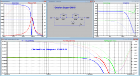
It is a shame you can't electronically brake a cartridge. Attached is one of Hans measurements from the cartridge dynamic behaviour thread. the first graph and the equivalent model are the interesting parts. This is for an Ortofon superOM as an example of a relatively well behaved generator.
Attachments
I'm not talking about magnitudes either, I'm just taking the reciprocal of a complex number and then calculating the real part. Suppose B = -1 mS and G changes from 0 mS to 1 mS. G/(B^2 + G^2) then changes from 0 ohm to 500 ohm, so it doesn't get smaller at all. If you keep increasing G, eventually G/(B^2 + G^2) will tend to zero again, but we were discussing the effect of a parallel conductance with a finite value, not the limit for infinite parallel conductance.
I should have written abs(G) << abs(B) though, rather than G << B.
I should have written abs(G) << abs(B) though, rather than G << B.
Last edited:
Other than headroom limitations, anyone want to comment on this design? using the LSK489 as the input in front of a LM4562?....
Many-many Japanese flagship Hi-Fis used essentially this plan, albeit with their own house devices.
OK, Pioneer A-757 by my side put the RIAA in the first loop, then rumble then a final fix-up stage.
Headroom is not an issue in the LSK-487 plan, it only takes flat-gain of 10 in front. There's not really over 100mV from any music in your grooves, and the opamps have near 20dB over that.
And a JFET frontend will tolerate that 0.1uFd input cap (which may be virgin parchment or other exotic). A BJT will rumble like a pack of B-17s with that much impedance in its Base loop. (I have seen BJT 1/f noise from too-small C1 trip woofer protection.)
Attachments
Many-many Japanese flagship Hi-Fis used essentially this plan, albeit with their own house devices.
OK, Pioneer A-757 by my side put the RIAA in the first loop, then rumble then a final fix-up stage.
Hello PRR
That's an interesting circuit snippet. It's obviously designed to handle both MC and MM inputs, hence the ingenious gain-switching as well as the FET input devices. I note that the RIAA upper roll-off is wholly passive. (R541, R543 and C515) I am however slightly puzzled by L501- it seems rather big for an EMC component.
> obviously designed to handle both MC and MM inputs
I should have mentioned that. I once understood most of it, but rarely use it now, and only at MM-flat. It is VERY impressively built inside, and while I know form from function, I just accept that some Japanese Geeks sliced and diced every detail to their satisfaction (or budget limit).
I have seen a similar ploy, reduced to two 10-cent FETs and a 13-cent chip, in some very low-cost phono stages. It can give a published noise spec better than a 2-buck chip. That might swing a sale.
If you read a lot of schematics, you will find the composite amp plan used a lot.
I still like 2-transistor (no chip) RIAA (albeit with a Darlington in the 2nd stage) but that's just me.
- Status
- This old topic is closed. If you want to reopen this topic, contact a moderator using the "Report Post" button.
- Home
- Source & Line
- Analogue Source
- The LM4562 in a phono stage.