If you record and play back on the same machine, you still need to follow the standard, right? Now taken that the record path has no EQ and is fairly linear (since the head is current driven), why is it necessary to equalize the playback with a corner frequency somewhere in the middle of the audio band? Why not just a simple -6dB/octave EQ, starting let's say at 30 Hz?
If I understand the question right, you are asking, why use equalization at all? Just record and playback flat, with a little HF lift for head inductance losses?
In the confusing language of technical writing it is difficult to find a clear answer but I believe it has to do with the following:
— Tape noise at different frequencies and its objectionability
— Frequency content of music
— Ability of flux to hold different frequencies
So equalization is a compromise effort to make the most of tape given the above. For instance there is little musical content above 12kHz, so you can boost a bit more and make up less for head losses to reduce noise.
If you do read old literature on the subject, you will see that there was much disagreement on what was right.
No, I mean there is a bass roll-off @50Hz and a treble boost @3150Hz at playback. Consequently there must be a bass boost (@20Hz?) to @50 Hz at record. The treble boost should be due to the head gap natural rolloff , but my question: is the rolloff starting at the same frequency for all replay heads? Why could the 50Hz upper corner frequency be standardized, and not let the manufacturer of each tape recorder adaptt it for their particular replay head?
lcsaszar, that is the good question.
For cassette decks there are standard time constants, but every manufacturer make their own EQ that is close to standard but not exactly the same.
It is probably because the different heads they use.
Bigger differences are in the high frequency lift, compensation of gap loses, this part of EQ is not regulated with any standard, and some manufacturer like Nakamichi here use aggressive treble lift.
> why is it necessary to equalize the playback with a corner frequency somewhere in the middle of the audio band? Why not just a simple -6dB/octave EQ, starting let's say at 30 Hz?
Response rises, but not to infinity. It rolls-over into a NULL.
Tape is expensive. We wish to extend usable frequency response as close to the null as possible. Gap-loss becomes significant two or three octaves below the null. If we correct most of that we use 4X-8X less tape, a very significant savings.
We can not correct ALL that loss in the recorder, it is too much.
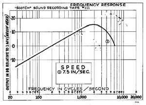
At 7.5ips the gap loss gets significant around 3KHz. Here we start the correction by flattening the integrator action of the preamp. This gives an effective 6dB/oct rise, correcting much of the first section of the gap loss. This has been standardized as a *playback* function. It gives another octave of good response, half the tape cost.
The recorder is expected to cover the remaining loss. This is typically a high-Q boost in the top of the audio band. Fancier machines will use fancier EQ and more boost to extend overall response to very-near the gap loss null.
This EQ scheme is well-considered and universally used in audio recording. Oh, the CrOx tapes have yet another corner choice different from rust tape, and 3M's master recorders tried a proprietary curve generally similar with small differences. But if you are not an expert, you *do* use the standard playback EQ.
See also:
http://mrltapes.com/mcknight_freq-resp-of-mag-recorders.pdf
Response rises, but not to infinity. It rolls-over into a NULL.
Tape is expensive. We wish to extend usable frequency response as close to the null as possible. Gap-loss becomes significant two or three octaves below the null. If we correct most of that we use 4X-8X less tape, a very significant savings.
We can not correct ALL that loss in the recorder, it is too much.
At 7.5ips the gap loss gets significant around 3KHz. Here we start the correction by flattening the integrator action of the preamp. This gives an effective 6dB/oct rise, correcting much of the first section of the gap loss. This has been standardized as a *playback* function. It gives another octave of good response, half the tape cost.
The recorder is expected to cover the remaining loss. This is typically a high-Q boost in the top of the audio band. Fancier machines will use fancier EQ and more boost to extend overall response to very-near the gap loss null.
This EQ scheme is well-considered and universally used in audio recording. Oh, the CrOx tapes have yet another corner choice different from rust tape, and 3M's master recorders tried a proprietary curve generally similar with small differences. But if you are not an expert, you *do* use the standard playback EQ.
See also:
http://mrltapes.com/mcknight_freq-resp-of-mag-recorders.pdf
Yes, PB curves must adhere to the standards. How the signal gets to that response does differ between machines, depending on heads and how accurate they want the play curve to be. Then there is the question of head bumps. At 7.5 ips the yhide in the bass frequencies, but run at 15 or 30 ips and they are front and center. Studer does "eq them out", but many makes don't make any effort to deal with them.
So the calibration routine generally follows the transport setup, speed, then standard levels and EQ for frequency response. Now you have playback calibrated and you set up the record characteristics starting with bias. Generally so many dB over the peak as you increase the bias level, followed by level and high frequency EQ. If you follow that procedure, you will be on spec and on standard. Most people use 250nWb or 320 nWb for the 0Vu level. From this you can see you would need calibration tapes. MRL still manufactures these, but they are very expensive.
-Chris
We can not correct ALL that loss in the recorder, it is too much.
At 7.5ips the gap loss gets significant around 3KHz. Here we start the correction by flattening the integrator action of the preamp. This gives an effective 6dB/oct rise, correcting much of the first section of the gap loss. This has been standardized as a *playback* function. It gives another octave of good response, half the tape cost.
The recorder is expected to cover the remaining loss. This is typically a high-Q boost in the top of the audio band.
When I painstakingly adjust a 4-track 7-1/2ips reel-to-reel and make tape and REALLY cannot tell between source and tape, I am always amazed how, despite all these shortcomings, with good engineering such performance is achieved.
In the "audiophile" world many claim "analog is better." It is not, of course, but nevertheless a wonderment how close it comes despite its almost impossibly compromised medium!
Hi toptip,
Well, I would have to say that it is amazing how good the performance of a R-R is without having to resort to the level of tricks used to make a Cassette sound good. As the track width and speed increases, things just get better and better, never mind more expensive.
One area where analogue tape is better than most digital format in use is the dynamic range available, and what happens when you exceed it. Very little sounds as bad as a digital channel that is clipped.
Each has their strong points, but if you want to see real performance, play with a Dolby SR module on a half track mastering machine!
-Chris
Most of the guys who have a professional Studer or Otari say that they never use any dolby at all...I personally found cassette with the latest dolby c chips good enough to color the best digital recording in a very pleasant way .I just use a 3head cassette player in loop listening to a cd player and that is for me the best cheap experience.
It is simple:
-C30 and R32 in parallel define 50Hz constant
-C30 and R31 define where the low frequencies start to rise, (2.2kHz in cassette decks).
-R33 is for gain.
-R33 and C33 define lowest frequency, it is HPF. (not part of NAB)
Hi,
Trying to understand this a bit better (and I know you have mapped this out for me in further down, thank you), I calculated the corner frequencies.
I see a 50Hz and a 1000Hz (which is not part of RIAA) but not 500Hz or 2200Hz. You mention that those are done elsewhere. I guess those are the other components you took out? why is there a 1000 do you think?
Attachments
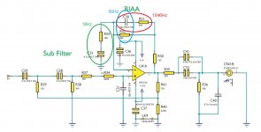
Don't know why Cambridge make this 1000Hz in RIAA preamp 
500Hz and 2200Hz (for RIAA) must be on the other part of the original Cambridge schematics.
R24 and C39 are part of RIAA.
In post 35 is my final version of NAB preamp from this RIAA.
You just calculate the values of R and C, or put values from datasheet app-note for LA3161.
500Hz and 2200Hz (for RIAA) must be on the other part of the original Cambridge schematics.
R24 and C39 are part of RIAA.
In post 35 is my final version of NAB preamp from this RIAA.
You just calculate the values of R and C, or put values from datasheet app-note for LA3161.
Last edited:
Your subsonic filter in front of the head amplifier will add noise. Better think about how to replace the subsonic filter with a low noise FET preamplifier with couple of dB gain, via a bi-polar capacitor in front of the operational amp. OPA827 may give better results since the current noise would dominate in your design ... then you can further add the subsonic filter at the output of the OPA827, without the need of a inter-stage separation capacitor ... for design examples check Nakamichi's Dragon either BX300 head preamplifier ... hope this helps. Good luck !
Last edited:
You can't just select two components in a network and derive a time-constant from them, the whole network affects the poles and zeroes, you have to do the full network analysis in the general case.
Might be mentioned in an earlier post (I've not read them all).
Everything is published by Lipshitz: On RIAA Equalisation.
I have a copy somewhere.
@ toptip, I realize this thread is more than 1 year old, but did you manage to convert your Cambridge phono preamp into a tape head preamp?
Only NAB 7.5 ips or multiple speeds? Also IEC EQ?
Currently I'm converting the MM input of the Cambridge 651P into a tape head preamp, NAB 7.5 ips. The EQ is done on 1 channel only for testing.
I'm using the Anti EQ module made by Pievox in Germany for testing the FR.
This module is developed to inject a constant current signal into the tape head connected to the preamp.
The Pievox module must be fed by an external frequency generator.
It works well to check the FR curve.
For testing noise, THD and SNR I have a QA400 from QuantAsylum.
However, I'm not sure what's the best method of attenuating the QA400 signal output into the range of millivolt range for the Cambridge input.
If I select -50dB output signal, the QA400 output stage noise remains the same and is then amplified by the tape preamp.
If I go through an external voltage divider, I get significant 50Hz hum harmonics in the frequency spectrum.
How are test signals generated for MM/MC phono inputs in general?
Alain
- Status
- This old topic is closed. If you want to reopen this topic, contact a moderator using the "Report Post" button.
- Home
- Source & Line
- Analogue Source
- Tape reproduce amplifiers