Let's talk about the design of analog tape reproduce amplifiers. These types of amplifiers are normally presented with a relatively weak input signal which can be less than 500 microvolts RMS for low tape speeds and narrow track widths, as is the case with compact cassette tapes. As a result, the noise performance of the reproduce amplifier can be somewhat critical. With higher tape speeds and wider tracks, however, the playback head produces a higher voltage, and a high signal-to-noise ratio is more easily obtained.
One factor that can degrade the signal-to-noise ratio is the input noise current of the input stage of the reproduce amplifier. Tape heads often have at least 50...150mH of inductance. As a result, their impedance is high at the higher audio frequencies. A noise voltage which is directly proportional to at least two factors--the noise current spectral density of the input stage, and the impedance of the playback head--appears at the input of the reproduce amplifier. The use of JFET's in the input stage can reduce this noise voltage due to a reduction of the input noise current compared to bipolar junction transistors.
Tape reproduce amplifiers usually have a special frequency response featuring a low-pass filter characteristic within some range of frequencies. The properties of the reproduce head (along with other factors) usually make necessary a non-flat frequency response of the reproduce amplifier in cases where a flat frequency response of the record/playback system is demanded. Different equalization curves exist for different tape speeds and for different types of magnetic tape. The playback equalization curve is normally described by one or more time constants, such as 3180us and 120us. It is common for the reproduce amplifiers of the higher speed tape machines to attenuate high frequencies to a greater extent than do the reproduce amplifiers in, for example, cassette tape equipment. This corresponds to a low time constant, such as 50us, for high tape speed. A time constant of 120us is typical for compact cassette tape.
An important difference between, say, 120us and 50us time constants exists as far as tape noise is concerned. When a 50us equalization time constant is used, the tape noise is low-pass filtered during playback between frequencies 1326Hz and 3183Hz. (*) These frequencies approximately correspond to the time constants 120us and 50us, respectively. At frequencies above 3183Hz, the tape noise is attenuated, relative to the case with a 120us playback time constant, by a factor that is mostly independent of frequency. The 50us time constant is normally used when playing back a tape which has been recorded at 15 ips (inches per second). This applies to the NAB equalization standard.
* It is normally low-pass filtered even below 1326Hz. The low-pass filtering effect typically begins at about 50Hz which corresponds to about 3180us. However, relative to the normal 120us equalization curve, there is no low-pass filtering taking place below about 1326Hz with 50us equalization.
It will be interesting to read what those with more experience with analog tape have to contribute, in this thread. Any guidelines and suggestions on how to make high performance reproduce amplifiers for reel-to-reel and cassette tape machines are appreciated. If you find errors or inaccuracies in what is written above, please let me know.
The first circuit shown in the attachments was designed by me a few years ago. I recommend that you use something better. The circuit has a problem with power on/power off transients and will put a voltage on the playback head when you connect and/or disconnect the power supply, creating a magnetic field in the head and partly overwriting any tape that is pressed against it.
Attachments
Last edited:
Thank you for your work and explanation. Most of the later pro tape machines did use FET's in their repro amps front end. A few used actual differential inputs - with an instrumentation amp-like configuration. Suggest you look at circuits in the later Otari's, Tascam's, Lyrec and Studer. BTW, shoot for 50db gain - just "about right" with typical 50 - 200mH PB heads. Turn on/off transients have to be dealt with "downstream" - I've not found them too bothersome.
You can also try the OPA627 op amp. Simple circuit; VERY nice sounding, if a tad "expensive".
And let us know your progress.
Charles
You can also try the OPA627 op amp. Simple circuit; VERY nice sounding, if a tad "expensive".
And let us know your progress.
Charles
Last edited:
Thank you for commenting! In fact, I was going to continue with a discussion of input stage topologies, including single device, differential, and complementary push-pull configurations. I might add some drawings, as well.
As for the OPA627, it is not exceptional in terms of open loop bandwidth. The OPA637 has a higher slew rate than the OPA627. Both of them have low current noise (about 0.0021pA/rt Hz at 100Hz). In principle, a discrete equivalent of either should sound slightly better than the integrated circuit.
As for the OPA627, it is not exceptional in terms of open loop bandwidth. The OPA637 has a higher slew rate than the OPA627. Both of them have low current noise (about 0.0021pA/rt Hz at 100Hz). In principle, a discrete equivalent of either should sound slightly better than the integrated circuit.
Oh well - just listening to my Stellavox with the head wired out to a 627 preamp. Bringing it to RMAF if you'll be there.
Sounds just fine to me - as do other 627 circuits I've tried including a phono and line level pre circuits. 637 has trouble at low gains. The LME series (49710 and others) also works well.
You are right that a discrete circuit can best it - look at some of the phono pre's described in this and other threads.
Charles
This is a 5-year old thread and I wanted to see what may have happened since.
A near complete absence of tape playback amps in the marketplace, compared to what looks like an over-saturation of phono / RIAA preamps, is particularly noteworthy.
I have often thought that converting an otherwise well-designed, quiet RIAA amp, especially one for moving-coil cartridges with their higher sensitivity, should be relatively straightforward but alas, it seems impossible to get service manuals or schematics for any that I have tried and reverse engineering a commercial product is beyond my skill set.
I also wanted to add one comment. The thread-starter above says, ”Tape reproduce amplifiers usually have a special frequency response featuring a low-pass filter characteristic within some range of frequencies” and goes on to discuss the various time constants.
This is true, of course, but one matter gets overlooked, perhaps because it is too obvious: the most important part of any equalization is a 6dB/octave downward slope, due to Faraday’s law, that induced EMF (i.e., by action of recorded flux on tape head) increases proportionate to flux change rate (or frequency). All other equalization is mild compared to this basic slope.
Of course all magnetic cartridges also require the same base slope, so converting a RIAA preamp to a tape replay amp does not need to involve changing that bit.
The discussions on tape machines don't get a huge traction here because there are at least two other forums specialized in tape machines or being run by recording professionals:
Tapeheads.Net Home Page
Gearslutz
Tapeheads.Net Home Page
Gearslutz
This is true, my current running Otari thread is not attracting much attention here. I'm also active over on tapeheads.
I'm not of the impression that the level of technical prowess is equivalent, here there are more technically capable hobbyists and professionals but almost no interest.
I'm not of the impression that the level of technical prowess is equivalent, here there are more technically capable hobbyists and professionals but almost no interest.
I have often thought that converting an otherwise well-designed, quiet RIAA amp, especially one for moving-coil cartridges with their higher sensitivity, should be relatively straightforward but alas, it seems impossible to get service manuals or schematics for any that I have tried and reverse engineering a commercial product is beyond my skill set.
Earlier in this thread its is said that the inductance of a playback head is typically 50 mH to 200 mH. If that's correct, a moving-magnet RIAA amplifier with modified equalization probably works better than a moving-coil RIAA amplifier with modified equalization. A moving-coil amplifier, especially one with a bipolar input stage, would probably have a too high input noise current and too low input resistance.
You'd think so, but all of the Otari decks I have worked on have bipolar op-amp front ends and the heads fitted work best into pretty high input impedances. (150K being typical on MX5050 for BII and MKIII decks I am most familiar with using NJM2043.)
Not on the face of it a good choice based on a quick look at the data sheet, but in practice it works pretty well.
Not on the face of it a good choice based on a quick look at the data sheet, but in practice it works pretty well.
Best cassette players have fet input(Nakamichi, Pioneer, Technics, Sony) , very high HFE/low noise input BJT(Tandberg) or m5220 -njm2043 (Pioneer, Technics, Denon, Aiwa), njm2068-NAD low noise bjt input op-amps .
Reel to reel tape machines have higher output so they can be handled by low noise bjt input easily.
It is true that there are very good professionals here that could drive meaningful discussions on tape machines, but on Tapeheads there are people more interested and passionate about it and passion is the one that drives people in the first place.I became addicted on tape machines for a year now and i have to admit that tape world is a whole world by itself.I need to force myself to get out of its magnetism")
Reel to reel tape machines have higher output so they can be handled by low noise bjt input easily.
This is true, my current running Otari thread is not attracting much attention here. I'm also active over on tapeheads.
I'm not of the impression that the level of technical prowess is equivalent, here there are more technically capable hobbyists and professionals but almost no interest.
It is true that there are very good professionals here that could drive meaningful discussions on tape machines, but on Tapeheads there are people more interested and passionate about it and passion is the one that drives people in the first place.I became addicted on tape machines for a year now and i have to admit that tape world is a whole world by itself.I need to force myself to get out of its magnetism
You'd think so, but all of the Otari decks I have worked on have bipolar op-amp front ends and the heads fitted work best into pretty high input impedances. (150K being typical on MX5050 for BII and MKIII decks I am most familiar with using NJM2043.)
Not on the face of it a good choice based on a quick look at the data sheet, but in practice it works pretty well.
There's nothing wrong with using a bipolar input stage as long as the collector bias current is properly chosen to get a decent noise match. For the extremely low source impedance of a moving-coil RIAA amplifier you would need a relatively high collector current (few milliamperes to a few dozen milliamperes), for a 100 mH source the optimum would be at a much lower current. I can't tell you how low, though, as I never did the calculations for tape equalization, but an educated guess would be around 100 uA to 250 uA.
Head impedance / preamp match
It probably depends on the type of head too, no?
Right now, for everyday testing of machines I renovate mechanically, I use one of these:
https://pubs.shure.com/view/guide/M64/en-US.pdf
They are plentiful on eBay, generally around $100 and do the job. I have recently been fixing a pair of 1960s RCA Cartridge players. Those run at 3-3/4 ips. I changed C12 and 13 on the Shure to 4nF to move the equalization constant. To my ears, the sound is as good as that vintage a machine will ever be.
But I would like to have something better for reel tape machines. This is apparently quite a good phono amp, has a bunch of “creature comforts” like muting, etc., and it is not crazy expensive:
Cambridge Audio - Alva Duo MM/MC Phono Preamplifier
But I cannot get a service manual or a schematic.
There's nothing wrong with using a bipolar input stage as long as the collector bias current is properly chosen to get a decent noise match.
I am afraid my one semester transistor course at school did not cover this subject: what is the relationship between noise, impedance and bias current? All we studied was to bias transistors “one diode drop” or 0.7V.
Well, with a BJT input stage you have to make certain your input bias current is very low. This is why FET input circuits are favored as they have practically no input bias currents.
Having said that, most BJT preamps use high collector currents for low noise. So, what does that mean for input bias currents? Same for the practice of paralleling several transistors for lower noise.
Yes, look at some of the more modern head amp designs for some state of the art designs.
It's too bad that interest in tape heads is low here, because I bet members here could design a far better head amp than is in common commercial use. Although, the least noise I've heard from a cassette deck PB amp has been the Nakamichi designs. Even their car head unit designs are very good in the upper models. The TD-1200 and 1200 MKII being no holds barred approaches to low noise designs. I'm interested quite a bit since I spent many years repairing and calibrating various tape machines including 24 track machines. These circuits are interesting.
-Chris
Nakamichi had the lowest impedance tape heads so you won't get the same results by applying their preamps to other tapeheads but you won't be very far either with appropriate compensation.Technics did only one playback head which was lower impedance than any other tapeheads, but with a very special construction in RS AZ-6, AZ-7 and too late... You have here a list made by A.N.T.: 53 heads for 3-head cassette decks measured and his site for more ideas: A.N.T. Audio :: Welcome :: Tape Recording He's one of the engineers who turned "audiophiles" so i take his advice with a bit of salt sometimes, but , as with anything else in life, natural selection makes the evolution
Hi dreamth,
Nakamichi heads were actually a Sendust formulation called Crystalloy. Just basically a basic Sendust head made to very close tolerances. It's also important to note that Nakamichi pushed the pressure pad in the deck back and away from the head. Tape tension was provided by the difference in speed of the two capstans, and by controlled back tension on the supply reel. Exactly like an open reel machine. The heads didn't have any form of tape guide either, allowing exact positioning of the head gaps on the tape.
The Glass heads (Ferrite) saturate easily, and they wear - just not like other heads. They get wavy across the surface, but the gap chips, increasing it's size. Permalloy is pretty much the same thing with all the other's faults.
I once tried to get warranty for a worn out glass head from Akai. They were not in a position to warranty the head as they didn't have spares. It was within the 5 year life policy that Canada has, so that nasty distributor couldn't live up to their legal requirements, let alone their own claims. I don't know if the support time is still 5 years in Canada, but they probably get around it with pro-rated replacement policies. Probably the entire industry these days. Consumer loses again, big time!
Its interesting that they made up that list. It would have been handy to have in the 80's and 90's.
-Chris
Of heads and tape tension
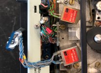
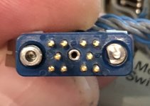
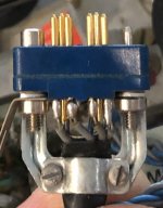
Few things. Of course I do not want to touch any of the FM electronics inside (yet) or cut off the original connector. For the moment I will use these PC pins I fashioned into clips but would like to find a matching female. The service manual calls it “Tuchel” but I could not see an Amphenol-Tuchel that looks like it. Also tuchel is sometimes used generically.
The heads. I had never heard of this manufacturer and could not find anything on the web.
Any enlightenment would be much appreciated.
On a related subject, I am thinking of trying this 1970s B&K 7003 instrumentation tape recorder to play audio tapes. It has 4-channel heads and plays at 1.5 / 7.5 / 15ips. It has double capstans for tape tension too.Nakamichi heads were actually a Sendust formulation called Crystalloy. Just basically a basic Sendust head made to very close tolerances. It's also important to note that Nakamichi pushed the pressure pad in the deck back and away from the head. Tape tension was provided by the difference in speed of the two capstans, and by controlled back tension on the supply reel
Few things. Of course I do not want to touch any of the FM electronics inside (yet) or cut off the original connector. For the moment I will use these PC pins I fashioned into clips but would like to find a matching female. The service manual calls it “Tuchel” but I could not see an Amphenol-Tuchel that looks like it. Also tuchel is sometimes used generically.
The heads. I had never heard of this manufacturer and could not find anything on the web.
Any enlightenment would be much appreciated.
Attachments
I am afraid my one semester transistor course at school did not cover this subject: what is the relationship between noise, impedance and bias current? All we studied was to bias transistors “one diode drop” or 0.7V.
Assuming that 1/f noise is negligible and that there is no popcorn noise, which is typically the case with good audio transistors, you have three main causes of noise at audio frequencies remaining:
1. Thermal noise of the base resistance. This produces a noise voltage at the input (assuming the base is connected to the input). You can keep this low by choosing the right transistor or by connecting a bunch of transistors in parallel (taking measures to ensure that the current is distributed equally between them).
2. Base shot noise. This can be modelled as a noise current source between base and emitter. When the impedance of the source that is connected to the base is zero, it can just shunt the base shot noise current without any effect on the signal to noise ratio. When the source impedance is nonzero, this noise current causes a noisy voltage drop across the source impedance. The higher the impedance, the more effect this has on the signal to noise ratio.
Countermeasures against base shot noise: anything that keeps the base current low, that is, using a transistor with high hFE and biasing it at a low collector current.
3. Collector shot noise. This can be modelled as a noise current source between collector and emitter, but with some mathematics you can transform it into an equivalent noise voltage source at the base. This equivalent noise voltage gets smaller with increasing collector current.
All in all, assuming a single-transistor input stage and neglecting the effects of 1/f noise and self heating, for a given transistor and given source impedance, there is an optimal collector current:
IC,opt = (kT/q)/re_opt
re_opt = (Zs + rb'b)/sqrt(hFE)
with
kT/q ~= 26 mV at room temperature
rb'b the transistor's base resistance
Zs the source impedance
hFE the transistor's DC current gain
When you connect N transistors in parallel, rb'b is 1/N times the base resistance of a single transistor and IC,opt is the sum of the collector currents of all N transistors.
Complicating factor for moving-magnet and tape head amplifiers: Zs varies a lot over the band of interest.
JFETs are easier: just take a high transconductance FET, check its datasheet to see that it doesn't have too much low-frequency noise (1/f or G-R noise) and bias it at a large current.
- Status
- This old topic is closed. If you want to reopen this topic, contact a moderator using the "Report Post" button.
- Home
- Source & Line
- Analogue Source
- Tape reproduce amplifiers