The MK3 and SP-10R do measure better than a MK2 on the same bench with the same JVC test record. I have not measured that amount of speed drift using the same part of the same test record. My frequency counter is locked to a HP GPS frequency standard with a Rubidium source as a backup.
Dave those figures were out of the manual, I'm retired now so don't have access to the calibration lab setup I had when working all frequency measurement was referenced to the NMI Rubidium. I do have a HP 5316B but no external reference.
If the mk3 and 10R measure better then what measures better?
Unfortunately I can't measure the SS/Delrin platter I made as it doesn't fit a stock SP10
If the mk3 and 10R measure better then what measures better?
Unfortunately I can't measure the SS/Delrin platter I made as it doesn't fit a stock SP10
.
W&F is slightly, but only slightly better on the MK3 and 10R. The 10R pulling away very, very slightly.
I use the DIN 45 465 and JVC TRS1002 test records with multiple copies of each. The results vary depending on the weighting used and all 3 are very close with the MK3 and 10R always the better.
Noel Keywood of HiFi World, Paul Miller of HiFi News and at least one other here, have results similar to mine. The weighting of the measurement is also a factor and you may have seen HiFi World recently also quoting JIS as I recently suggested to Noel. No turntable has measured any better.
Using an Agilent 5131A driven by a HP 58503B GPS (option 001) with a back up Datum Rubidium source I was not able to determine any reliable and measurable drift with is to be expected from a crystal controlled PLL over a short period.
We are so very close to the limits of measurably that any better turntable would be difficult to prove IMHO. I do wish the 10R had a bearing of the same size as the MK3 however.
Once again YMMV Dave
Thanks Dave,
I have a fair amount of time on my hands so I have been looking at ways to improve a mk2, mk3's are rare and expensive. The mk3 bearing is huge and the way it's attached to the motor is extremely rigid. This got me thinking that the weak points in the mk2 are most likely the bearing and platter, the bearing housing flexes and the platter rings. If these are the major weaknesses they are not expensive to fix.
I have disassembled the motor and will be purchasing some 7075 (or 6061 if I cant get 7075) to machine a new motor housing with a larger bearing spindle and housing. I think a 12mm spindle will be the largest I can get up the FG.
W&F is slightly, but only slightly better on the MK3 and 10R. The 10R
Noel Keywood of HiFi World, Paul Miller of HiFi News and at least one other here, have results similar to mine.
You can name me Dave, no problem.
We are so very close to the limits of measurably that any better turntable would be difficult to prove IMHO.
I’ve an idea for a different way to measure. Maybe over winter break I can spend some time on it.
I’ve an idea for a different way to measure. Maybe over winter break I can spend some time on it.
Measure the FG signal, you could also do this to measure dynamic W&F caused by groove modulation.
Drift is 0.002% and W&F 0.035%. I'm struggling to see how modern electronics will improve a mk2?
It possibly won't BUT 40 year old electronics does have a habit of failing. So having a way to keep things running is a worthwhile exercise, and a bit of fun. I am with you that the limitations are mechanical and, given that for domestic use none of us NEED the SP10 party trick of 250ms from stop to lock the coreless motor of the 10R is the next logical step.
From measurements JP has done (who I believe has as many SP10s as I have children) whilst the mk3 is better than the mk2 in measurements even a well fettled SL1200 is at the point of measuring the accuracy of the cutting lathe motor.
But it's all fun to explore these backwaters, and turntable DIY is nothing if not obsessive

Sorry JP that was meant as a question.........
NP. Ideally I want something that couples mechanically but reads like a W&F tone. I prefer polar plots as I can see a lot that gets hidden in a W&F measurement.
It possibly won't BUT 40 year old electronics does have a habit of failing. So having a way to keep things running is a worthwhile exercise, and a bit of fun. I am with you that the limitations are mechanical and, given that for domestic use none of us NEED the SP10 party trick of 250ms from stop to lock the coreless motor of the 10R is the next logical step.
IME those logic PCB IC's are extremely robust and also still available in fact all components in the SP10 are still available. If you go down the path of a micro controller upgrade, what happens in X years when the code/µcontroller are NLA.
The mk2 is ultimately repairable and the last development I had done on a µcontroller/software system cost $60,000AUD 20 years ago. Unless JP or some other DIY folk develop this it would be cost prohibitive. It's not like what JP did for the mk3 in developing a replacement chip it's a complete re-engineering job of the control electronics.
I'm about to go down this rabbit hole now. I have a spare mk2 that has the motor disassembled and is ready to go in a plinth. Electronics will be housed in a separate chassis (not the mk2 chassis).
Kaneta copy?
Last edited:
Time to out myself as the member for whom Warrjon has constructed the SP10mk2 platter in post #1614.
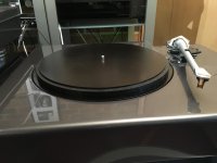
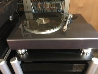
I have previously described my Kaneta style plinth in posts 1275, 1488 and 1528 and the discussions which followed. The final step is to replace the OEM platter, which has a clearly audible ring, despite the rubber damping layer. Warrjon is delivering the new platter in a couple of weeks and we will make some noise and impulse test measurements to try and quantify any differences in the platters mounted on the resin-bentonite plinth.
Here are some photos of an mdf mock-up of the new platter compared to the stock platter.
Attachments
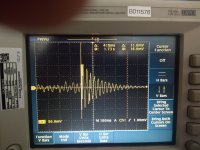
Here are some preliminary tests on my SP10. Stock chassis in a resin/bentonite plinth. I did this to set a baseline so when we do the measurements on Bon's TT I can also compare it to remote motor mount with his stock platter and mat. There are some variables note: Tonearm/Cart and phono-pre, but hopefully we can correct for these.
Methodology
Stylus resting in the groove of a stationary LP (an old LP)
6mm steel ball dropped from 300mm above the platter onto the edge of the LP.
Output taken from the Phono-pre.
First photo is the stock rubber mat.
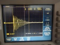
Second photo is my acrylic mat with reflex clamp.
While the decay time is for all intent and purpose the same what differs significantly is the level of the initial shock.
Methodology
Stylus resting in the groove of a stationary LP (an old LP)
6mm steel ball dropped from 300mm above the platter onto the edge of the LP.
Output taken from the Phono-pre.
First photo is the stock rubber mat.
Second photo is my acrylic mat with reflex clamp.
While the decay time is for all intent and purpose the same what differs significantly is the level of the initial shock.
Attachments
Kaneta copy?
Not sure what a Kaneta plinth is. I will be mounting the motor in a resin plinth and the electronics in a 2U rack case.

- Home
- Source & Line
- Analogue Source
- The Incredible Technics SP-10 Thread