I have never bought into the slate argument. Most proponents just state the superior damping properties, whereas the measurements of Cat Squirrel show otherwise.
I am not in the mass is better brigade. I have read Cat's site.
When I bought the TT I did not know what the plinth was made of I just assumed wood.
Problem I see with mass is it lowers the resonant frequency and low frequencies have far greater amplitude than high frequencies. These low frequencies get modulated onto the signal so adding a subsonic filter on the output of the TT does nothing. They need to be damped before they get to the TT, this seems to be where resin/bentonite works well.
Woah, Dude!! That is such a no-no.The seller shipped the unit with the platter on and the CW on the tonearm
"low frequencies have far greater amplitude than high frequencies"
Huh? I think what you said is not what you intended.
Ooopps I meant energy
I think the Denon arm is toast, I am not familiar with this arm but it is quite loose at the rubber damper.
Anyway I have just given the eBay seller a serve and we'll see how they respond. They do have 100% + feedback with a couple of 1000 transactions.
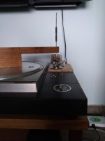
I made a couple of jigs with 235mm hole centres to mount the EPA-100, it's not ideal but at least got me spinning vinyl.
WOW even with this not ideal setup it sounds far superior to the RP8 and Apheta 2.
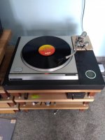
It tracks all but the most heavily modulated track on the HFN test LP although I did have to increase VTF to 2.0g. I have the EPC205C mounted with a Jico SAS/B stylus. Can't wait to get the bentonite plinth finished.
Anyway I have just given the eBay seller a serve and we'll see how they respond. They do have 100% + feedback with a couple of 1000 transactions.
I made a couple of jigs with 235mm hole centres to mount the EPA-100, it's not ideal but at least got me spinning vinyl.
WOW even with this not ideal setup it sounds far superior to the RP8 and Apheta 2.
It tracks all but the most heavily modulated track on the HFN test LP although I did have to increase VTF to 2.0g. I have the EPC205C mounted with a Jico SAS/B stylus. Can't wait to get the bentonite plinth finished.
Attachments
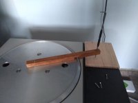

10 inch tonearm fit best, pleasing to look at.
That is an EPA-100 it is a 10" tonearm. But I had to mount it further back so it fit in the hole in the plinth, this made the arm loser to the SP10 frame.
I am loving the SP10 and EPA100/EPC205
I have more hours on it in 4 weeks than my RP8 had in 6 years.
I have put the plinth build on hold while I finish off a Ladegaard air bearing tonearm. Once I get the mounting of the arm finalised I will build the bentonite plinth to suit, it will have brass blocks cast into the back for mounting.
I have more hours on it in 4 weeks than my RP8 had in 6 years.
I have put the plinth build on hold while I finish off a Ladegaard air bearing tonearm. Once I get the mounting of the arm finalised I will build the bentonite plinth to suit, it will have brass blocks cast into the back for mounting.
I have more hours on it in 4 weeks than my RP8 had in 6 years.
I am not surprised in the least.

"low frequencies have far greater amplitude than high frequencies"
Huh? I think what you said is not what you intended.
You have to quite careful here. For sound waves in a gas amplitude is normally taken to mean pressure amplitude (as in the acronym SPL), which is directly related to energy. For strings and membranes and sheets vibrating we normally associate displacement with amplitude, but displacement amplitude is dependent on wavelength as well as energy, ie it does increase at longer wavelengths for the same energy.
Anyone out there understand FET's ?
I have a sp10 here that suffered the 32.5v and 5v lines coming together. I have fixed the logic board and its running again. BUT it doesn't phase lock. I think the problem is on the Control board, as replacing it with another it locks just fine.
After much head scratching, I think the problem is around the phase sample and hold section. The voltage on TR153 source seems higher than wanted, at 15v instead of the marked 11v, and the voltage on its drain hardly moves at all as the trigger pulse moves across the ramp.
If I disconnect R137 so the phase lock is disconnected all together it makes very little difference and it runs at or about the expected speed so all that seems to be ok. There is something odd going on as when the trigger pulse falls off the end of the rap, it does give a kick so there is something going on, but not enough to provide any feedback and lock on the phase position.
I have tried modelling the part of the circuit in Spice, and theer seems to be some odd interaction between the fet input capacitance and the 2200pf cap, I seem in spice to be able to reproduce the odd situation where there is 11v on the FET's gate (TR153). Using a scope probe is adding too much of a load so the 2.2nf cap discharges.
Maybe I should look out for a high impedance voltmeter and see if that shows whats actually on the gate. Its as if the voltage is building up on the 2n2 cap but going higher than expected but not falling back down again.
FET is basically a tap that is on and bias turns it off, so with a meter on Diode you will have 0.7v D-S and OL G-D and G-S.
I'd ignore the DC voltage and concentrate on the waveforms, you'll need 10x1 probes as the capacitive loading will effect the CCT. These feedback ccts are notoriously difficult to fault find.
Check all the waveforms, where the waveform is not as shown check the transistors in the block. You will need to pull them out of the circuit to check properly.
FET is basically a tap that is on and bias turns it off
Yes, I get that, but it was the bits at the edge of "basically" I was asking about. More looking yesterday is making me think its working at the moment more like a one way tap, seems the cap can be charged up, but when needed is not discharging. Increasing the capacitance to 7nf or so (to reduce the effect of the probes) and adding a 10M meter probe it starts phase locking. Even on *10 the scope probe seems to drain it too fast.
My theory is that the 10M or so of the DVM is allowing the cap to run down and the fet is topping it up, fet on its own seems to be working more like a one way valve and its charging up to the peak of the ramp voltage every time. I am going to check the duration of the pulse on E12, looks to me like it should be 600ns or so (anyone has any measurements?). Will see what it actually is, I wonder if its too short and its not allowing the cap to follow the ramp voltage properly.
Other than that everything looks fine, the waves and voltages (apart from the one of the driving FET) all look perfect.
I have just dug out the CCT and 15V is the result of the voltage divider of 91k and 18k so I would suspect TR153 could be faulty.
But before you go any further try adjusting the period. I bought an SP10 that someone had tried to get going and the after I replaced a definitely faulty TR129 the period adjustment was so far out the TT would not lock. I had to adjust the period multiple times, once I did this the TT locked on all speeds.
But before you go any further try adjusting the period. I bought an SP10 that someone had tried to get going and the after I replaced a definitely faulty TR129 the period adjustment was so far out the TT would not lock. I had to adjust the period multiple times, once I did this the TT locked on all speeds.
I have just dug out the CCT and 15V is the result of the voltage divider of 91k and 18k so I would suspect TR153 could be faulty.
I make 32.5v across 91k and 18k giving 5.34v not 15v, ( 18000 * 32.5 ) / ( 91000 + 18000 )
But the FET's were my first thought, I have replaced all four of them (before I posted, that was my first thought) and exactly the same results. The voltage on the ramp test point seems perfect, but TR129 is in the area so may be worth swapping just to be certain.
Oops I just went back and looked at my SS I typed 78k instead of 18k.
Are the replacement FETs 2SK30A or did you use substitutes? I could not get substitutes from RS et al and ended up buying a handful of genuine 2SK30A from eBay.
Have you checked the 32.5 and 5 volts with the TT running just to make sure that these are good, check ripple too.
As I said earlier I would ignore DC voltages and concentrate on the waveforms. My SP10 had multiple faults and had been modified so it took me a few hours to get it working and I found the DC voltages did not match the CCT in all cases but the TT worked correctly.
Yes, I used the correct FET's. Problem has been solved by replacing C229 on the logic board. The pulse was about 40ns, replacing the cap has increased it to 55ns and its all working perfectly, so I am guessing that the difference with the control board that worked was a slightly faster operating sample and hold.
Surprisingly I can reproduce the behaviour in spice, if the pulse is too short the 2n2 cap charges up and stays high, widen the pulse and it starts tracking the ramp.
Thanks for your suggestions.
Surprisingly I can reproduce the behaviour in spice, if the pulse is too short the 2n2 cap charges up and stays high, widen the pulse and it starts tracking the ramp.
Thanks for your suggestions.
I asked a long time ago if anyone was aware of a motor control system using more modern technology and easier to obtain devices. I had no answer to this query. Has anything changed? It seems somewhat shortsighted to have to rummage around the Oriental dealers to buy a few transistors/controllers etc. I am positive that therwould be a ready market for such designs....I am not interested in historical integrity - only in having a superb TT which is capable of taking many extremely expensive TTs to the cleaners once properly mounted and set-up. I would be perfectly happy with a two speed controller.
- Home
- Source & Line
- Analogue Source
- The Incredible Technics SP-10 Thread