Never understood why the SP-10 has no overvoltage protection at the input for its supplies. If something goes wrong with the external supply, it can generate well over spec voltage and fry the electronics. The supply fuses are of no help, by the time they blow, the table is gone... A recap of these old power supplies is a must, before connecting it to the table! I'll certainly install an overvoltage protection on the 5V digital supply. The others supplies goes to transistor/analog/power stage that will survive and incorrect supply, not the digital section with the 5V supply though!
a large wattage Zener diode of the appropriate voltage (> 5V) would do the job.
Even though there is a cable and connector and a separate chassis, the threat to the 'table's electronics is, IMO, no different than if the supply was in the base of the turntable. The fact that it's in a different chassis doesn't inherently make it more likely to stop regulating at the proper voltage.
Even though there is a cable and connector and a separate chassis, the threat to the 'table's electronics is, IMO, no different than if the supply was in the base of the turntable. The fact that it's in a different chassis doesn't inherently make it more likely to stop regulating at the proper voltage.
n10 are 100pF loading capacitors for moving magnet cartridges.
For the start stop you will need to go through this with a scope and the service manual. It would help if you have the SH-10C circuit, but I think you could do it without that.?
Loading capacitors, what purpose do they fill? I have never seen a setup like that before. Can i use any MM cartridge with these?
Start/stop: Okay, thats over my limit. Im decent in following instructions and doing simple soldering but not much above that.
There’s a bolt in most headshells that lets you rotate them?
But a small spirit level for headshells and adjust until level.
If the headshell won’t adjust you need one that does!
Thanks! That helped. Kind of embarrassing. But never had this issue before!
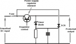
Yeap, exactly the kind of circuit I was planning to install on the 5V. And BrianL I agree that a separate power supply isn't different from one built in, but the catch is often that you can use the table with an other power supply, and this one can be defective... The crowbar circuit is fail safe, fast, blow the supply fuse and protect the table. It was used a lot into big, expensive HP test equipment power supplies in the 80's. Work like a charm... Anyway once I'll complete the repair on my second SP10, I don't want to have to do it again!
If these were as common as USB chargers and with as profligate use, then I'd agree that there is protection needed. I wouldn't expect the average SP10ii user to be mixing and matching multiple supplies and turntables -- few of us have more than one of each. If so, one should certainly make sure the supply works before plugging it into the turntable.
I'm quite familiar with what we at HP did with power supplies in the 80s. Generally those SCR crowbars were to protect the instrument from someone who plugged their device into a 220V circuit when the voltage selection switches were set to 120V. That's a much more likely scenario that mixing and matching 'random' SP10's and their supplies in 2018.
I'm quite familiar with what we at HP did with power supplies in the 80s. Generally those SCR crowbars were to protect the instrument from someone who plugged their device into a 220V circuit when the voltage selection switches were set to 120V. That's a much more likely scenario that mixing and matching 'random' SP10's and their supplies in 2018.
SP10 Mk2 speed problems quick fix
This fixes just about all Technics SP10 Mk2 speed problems. Takes a few minutes.
In the SH-10E power supply:-
On the 5v rail:
1. Replace C411 (100uFd / 16v originally) with any value above 150uFd and 16v that will fit (I use 200uFd 16v) (this is sometimes the only mod you need to make).
2. Solder an additional 1,000uFd / 16v capacitor across C410 (1,000uFd / 16v originally); LEAVE the old cap in place, it's usually OK, just old and tired. Make sure polarity is OK. Only replace if leaking (unlikely).
If it still cogs, then on the 32.5v rail:-
3. Solder an additional 1,000uFd / 80v capacitor across C413 (1,000uFd / 80v originally); LEAVE the old cap in place, it's usually OK, just old and tired. Make sure polarity is OK. Only replace if leaking (unlikely).
99% of the time this works. If it still doesn't, get back to me.
So every diagram says 16v 100
My caps read 50v 100 fitted.
I have enough of either to fit so which would be best? Fit like for like and go 50 (ignore the manual).?
The replacement for 414 are actually 560uf and 50. My board just has 50v and 100uf for the four caps 411 to 414.
Or I have 16v 680.
My caps read 50v 100 fitted.
I have enough of either to fit so which would be best? Fit like for like and go 50 (ignore the manual).?
The replacement for 414 are actually 560uf and 50. My board just has 50v and 100uf for the four caps 411 to 414.
Or I have 16v 680.
Last edited:
") , get the correct parts to fit in the space available.
, get the correct parts to fit in the space available.Alright, after being gone for quite a while, I managed to get myself back on the SP10...
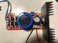
Found the problem to be a bad PSU, so I built one based on MPBarney’s blog and 2 cheap PCB’s from eBay.
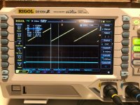
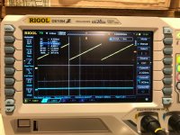
Voltages are correct and stable with the TT connected, so now I’m trying to set the PLL with a Rigol scope I picked up some time ago...
But I ran into a second problem.
I do get the correct waveforms on all three speeds and both channels, although the channel 2 waveform seems to fluctuate overtime (voltage increases/decreases) on all 3 speeds.
Turning trimmer 101 and 102 just adjusts the speed in which they fluctuate. The turntable refuses to lock, so speed isn’t consistent.
Am I still making sense? Anyone suggestions on what to look out for?
Anyway... Will post pictures later, when I get my laptop out of my luggage.
Found the problem to be a bad PSU, so I built one based on MPBarney’s blog and 2 cheap PCB’s from eBay.
Voltages are correct and stable with the TT connected, so now I’m trying to set the PLL with a Rigol scope I picked up some time ago...
But I ran into a second problem.
I do get the correct waveforms on all three speeds and both channels, although the channel 2 waveform seems to fluctuate overtime (voltage increases/decreases) on all 3 speeds.
Turning trimmer 101 and 102 just adjusts the speed in which they fluctuate. The turntable refuses to lock, so speed isn’t consistent.
Am I still making sense? Anyone suggestions on what to look out for?
Anyway... Will post pictures later, when I get my laptop out of my luggage.
In the attached images, you can see the wave of channel 2 decreasing. It's more obvious in the 78 rpm setting, but happening at the 33rpm as well...
Picture of the 5V PSU board included as well, I use a 10 turn trimmer. I find it helps with precision.
Picture of the 5V PSU board included as well, I use a 10 turn trimmer. I find it helps with precision.
Attachments
At this point the TT’s start/stop switch started acting up. Switch functions when tested with a DMM. I can select the 3 speeds, and start the SP10, but it won’t stop turning when pushed to stop.
So I started measuring some things following the fault-finding flowchart... Unfortunately it doesn’t really give me answers.
As the speeds are off, I followed point (D): TT rotates abnormally.
Voltage at point e15 = 27,4vdc. 0,4vdc high so I measured TR115~118 and D101, 106 and 107
D101: Anode 27,71
Kathode 27,09
D106: A 6,62
K 5,919
D107: A 0,004
K 5,918
Tr115: E 0,04
C
B 0,778
Tr116: E 0,004
C
B 0,07
Tr117: E 0,004
C
B 0,08
Tr118: E 8,02
C
B 6,62
All of the transistors are way off... didn’t measure the collectors, bit fiddly to reach without a steady hand.
Anyone got any tips as to where to start looking? Would be greatly appreciated.
- Home
- Source & Line
- Analogue Source
- The Incredible Technics SP-10 Thread