It now spins backwards!
I burst out laughing when I first saw it was turning backwards because I hadn't seen a turntable ever spin backwards. It just means more troubleshooting lies ahead.
After weeks of not doing anything, I finally put the bearing back together. The ball had some sort of residue on it on the shaft side, and it wasn't easy to wipe off. When pushing it back in, I just reversed it. Cleaned the innards of dust while the back was open and then put everything back together. After assembly, the platter spins smoothly. Connected the supply, turned it on, and it started spinning counter-clockwise.
Looking at the service manual, I checked the voltages coming out of the power supply. Next step is to measure things inside the table itself, which will take some setting up. The ad said the PSU was recapped, except the large motor cap, and a spare was provided. I soldered the new one in, but it does not make any difference.
The funny thing is it spins at the right speed at all three speeds. If I get it going in the clockwise direction, and then hit the start button, it keeps spinning in the same direction, but spins too fast.
The service manual actually has a section on turntable spinning backwards, and the next step is to check the waveform at e13. I don't have a scope currently, but I am looking at some of the cheap USB scopes. Any other suggestions? Anyone else face this issue?
I might just have to dig out an old Tek scope that a friend gave me. We recently moved, so, it is in storage somewhere. If it works, great, but if it doesn't, then I might look at the Rigol scope though I would like to avoid spending $350. I have used scopes at work, though not regularly or recently. I'm sure I can figure it out.
What do you mean by the strobe being locked? The neon bulb is not working and haven't replaced it yet. Based on a printed strobe disc, it looks pretty stable at 33.3 and 45 rpm.
What do you mean by the strobe being locked? The neon bulb is not working and haven't replaced it yet. Based on a printed strobe disc, it looks pretty stable at 33.3 and 45 rpm.
Hello! Im Nick from Greece and thats my first post here ")
I bought some months ago a sp10mk2 p/l in realy nice condition from ebay. Before i build the plinth for it i open both the motor unit and the psu to check the electronics inside (i love these things). Well inside the motor unit all the caps where good but inside the psu i saw a small leak on the large capasitor... So i send the turntable for a recap to one of the greatest electronic guys here in Greece. The recap was done succesfully as the adjustments also. After all these i made a plinth and i place the turntable and the tonearm. So i realise 4 problems in my sp10 (that maybe existe even when i bought the turntable).
1. The psu gets hot , more hot than my tube phono preamp ear834p
2. The is a very very small back and forth drift in speed, maybe its not drift but the strobe lines of the platter are not rock solid stable! They look more stable after some hour of working but still there is that back and forth looking drift. Maybe the platter is very very little bend? Dunno.
3. When the psu is open and the turntable is not spinning , when i press the 78 speed button (before i press the start) the strobo shows a little weak in light. On 33 and 45 looks ok
4. One night after playing more than an hour, the speed drifts for 3-5 seconds.
Any suggestions?
Ps: the voltages from psu are perfect, and there is very little wear at the thrust pad.
First, if you haven't done so, go to vinylengine.com, register and download the Technics service manuals that are archived on the site. If you can solder some appropriate-size resistors to a 4-pin XLR connector, you can operate the power supply without the turntable connected and with a small load -- that way you can make sure that the problem isn't with the power supply itself. If it seems good, then start the troubleshooting of the electronics in the turntable by checking all the voltages.
Not necessarily. But it's not uncommon for regulators to 'want' some minimum load in order to operate correctly. I would hope that since the supply and turntable can be disconnected from each other, the supply's outputs would be stable with no load. Adding some amount of load is nice but not necessary, I believe.
Another thing to do would be to check the supply voltages with the turntable connected and running (before it starts misbehaving). Assuming that the no-load measurements are in spec, they should not vary much with the turntable connected.
Another thing to do would be to check the supply voltages with the turntable connected and running (before it starts misbehaving). Assuming that the no-load measurements are in spec, they should not vary much with the turntable connected.
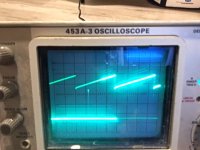
Update on backwards rotating table.
See the two images below. The strobe is set to 5 ms per div, and the two waveforms are exactly as in the service manual, with the delta T close to 6.3 ms. The strobe (which fortuitously came back on) is locked on at all three speeds. Just that it is spinning backwards.
If I rotate VR101, it goes back out of lock and visibly spins faster/slower and the scope shows the pulse waveform jumping around.
The caps in the PS have been replaced and all the voltages are good. I ordered new caps for all the electrolytics in the internal boards, and my next step is to start replacing one by one and keep testing. Start with the motor caps.
Any other thoughts or suggestions?
Attachments

If you're going to replace the electrolytics, I wouldn't waste time with changing out one-by-one. That is going to be a big pain and take a lot of time. I'd just swap all of them and see what happens. I doubt that in doing it one-by-one, you'd stop swapping if one cap magically cured the problem, so the only thing to be gained is to satisfy your curiosity as to the likely cuplrit.
Thanks BrianL, that makes sense!
Going through the troubleshooting flowchart again, I checked the voltages, and there is 4.95V on C2 at the connecting board. Can I consider that to be 5V? If it is under 5V, the flowchart says to check the constant voltage output circuit. The two variable resistors on the power supply board control the output voltages. The one controlling 5V is turned all the way, and I cannot get it above 4.95V. I was able to turn the 32.5V resistor to adjust that rail to exactly 32.5V (earlier, it was reading 32.7V). What are others measuring on the 5V rail? Is 4.95V within the margin of error?
Going through the troubleshooting flowchart again, I checked the voltages, and there is 4.95V on C2 at the connecting board. Can I consider that to be 5V? If it is under 5V, the flowchart says to check the constant voltage output circuit. The two variable resistors on the power supply board control the output voltages. The one controlling 5V is turned all the way, and I cannot get it above 4.95V. I was able to turn the 32.5V resistor to adjust that rail to exactly 32.5V (earlier, it was reading 32.7V). What are others measuring on the 5V rail? Is 4.95V within the margin of error?
- Home
- Source & Line
- Analogue Source
- The Incredible Technics SP-10 Thread