I thought about the lead gasket between the arm base and plinth. But I didn't implement it as there is little to no improvement in energy transfer.
There will be 6% reflection at the arm lead boundary and 65% at the lead plinth boundary. The lead is thin so almost all of the energy will be reflected back to the arm base.
My EPA100 is connected directly to the plinth with no gasket. I also don't use the stock EPA100 base, I made a new more rigid base from aluminium. The plan is to modify the plinth so it uses aluminium arm boards. The arm boards will be profiled on the top and holes drilled in the underside (not all the through) to breakup and scatter vibration energy.
Another thought I had was to laminate an arm board from aluminium and acrylic with the same profiling on the top and bottom layers of aluminium. The AZ of these results in about 50% reflection. The profile of the top and bottom scatters the energy wave causing it bounce around inside the arm board. If the wave hits the boundary at any angle other than 90deg the wave bends (just like light from air into water). The longer the energy stays in the arm board the more attenuation.
All this relies on the arm being able to effectively sink vibration into the arm board.

I thought about the lead gasket between the arm base and plinth. But I didn't implement it as there is little to no improvement in energy transfer.
There will be 6% reflection at the arm lead boundary and 65% at the lead plinth boundary. The lead is thin so almost all of the energy will be reflected back to the arm base.
My EPA100 is connected directly to the plinth with no gasket. I also don't use the stock EPA100 base, I made a new more rigid base from aluminium. The plan is to modify the plinth so it uses aluminium arm boards. The arm boards will be profiled on the top and holes drilled in the underside (not all the through) to breakup and scatter vibration energy.
Another thought I had was to laminate an arm board from aluminium and acrylic with the same profiling on the top and bottom layers of aluminium. The AZ of these results in about 50% reflection. The profile of the top and bottom scatters the energy wave causing it bounce around inside the arm board. If the wave hits the boundary at any angle other than 90deg the wave bends (just like light from air into water). The longer the energy stays in the arm board the more attenuation.
All this relies on the arm being able to effectively sink vibration into the arm board.
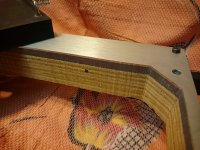
ive tried a few armboards, acylic,mdf/aluminium,ebony and panzerholz and also the tonearm bolted directly to my plinths panzerholz top plate,
the best by far and what i still use today is a CLD ( constrained layer damped) aluminium one.
Last edited:
To support the plinth ability as a sink for unwanted micro vibration, by padding the gap between the bearing cap and the plinth
a solution that follows the Artisan Fidelity method for the plinths of the SP 10?
The Artisan Fidelity SP10 mk2 page refers toa solution that follows the Artisan Fidelity method for the plinths of the SP 10?
"integral shielded bearing drain with our latest active "Quiet Core" technology."
"select low density woods in conjunction with anti magnetic metals"
I have no idea of the details, but they may be following the same principles.
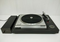
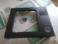
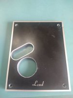
BTW, I found some pictures of the Lead Console SP10 mk2 plinth. I don't believe they use pure lead or the weight would be much greater than typically quoted. I have seen them come up occasionally on eBay. I have never been tempted though.
P2050767 | fanny2566 | Flickr
P2050766 | fanny2566 | Flickr
I have no idea of the details, but they may be following the same principles.
maybe Artisan simply used a more pompous name or removed the bottom cap and used a tip toe between the bearing sphere and the wooden base.

ive tried a few armboards, acylic,mdf/aluminium,ebony and panzerholz and also the tonearm bolted directly to my plinths panzerholz top plate,
the best by far and what i still use today is a CLD ( constrained layer damped) aluminium one.
A quick description of details of the CLD aluminum and maybe a pic would be nice.
Thanks,
Don
I have only seen images of the SP10 Mk II metal pressed/cast bowl that the motors stators are mounted in.
From the DD TT's I have stripped back, the SP10 Bowl is looking to be the most substantial in relation to the Wall Thickness.
The Base of the Bowl is also Quite Shallow in comparison as well.
The Bowl does have a additional form protruding from the Bowls Base.
The protrusion serves as the Bearing Housing that is seen at the lowest end with Threaded Cap.
The Threaded Cap extends to being being lower that the electronics PCB's.
Forming a piece of lead or using a Split Brass Ring to encapsulate the Threaded Cap and then incorporating another part that can clamp the lead/brass in place, as well as serve as an Anchor Point for a brace does not seem too awkward to achieve.
There will be a variety of ideas about what the Brace Material can be and how/if it should come into contact with the Threaded Cap.
A similar thought process can be put in place to decide the best methods for the lowest Anchor Point for the Brace and how that lowest Anchor Point should be coupled to the local materials.
The lead and brace working in conjunction with each other could prove to be a very useful modification on a standard Plinth Mounting for a SP10 Mk II, where improved rigidity for the Bearing Housing and the soaking energy away from the bearing housing is wanted.
The Link will show a off the shelf part that when the correct ID is selected can be used as the Clamp on the Threaded Cap.
An additional Plate can be produced with a Threaded Hole to be fastened to the Flanges.
This plate will serve as the Anchor Point for the Brace.
SHF8-60 Linear Slide Bearing Rail Support Shaft Table Motion CNC | eBay


A quick description of details of the CLD aluminum and maybe a pic would be nice.
Thanks,
Don
An arm board is not CLD. CLD is 2 pieces of thin sheet bonded with a viscoeleastic center. Approaching 4mm total panel thickness CLD effectiveness drops exponentially.
An arm board would be MLS (multi layer structure). This is where different materials of slightly varying Acoustic impedance and thickness are bonded together.
The modeling is complex, but put simply.
As sound reaches a boundary in the MLS some will be reflected and some will transmitted. If the wave hits the boundary at an angle the reflected wave will bounce with the same angle as the incident wave. The transmitted wave will bend as it passes the boundary dependent on the AZ between the 2 materials.
If the Material 1 is lower AZ than Material 2 then the reflected wave will be in phase with the incident. If Material 1 is higher AZ than Material 2 then the reflected wave will be out of phase.
Lastly - you will get far more improvement with a Kaneta plinth than the best arm board with a stock SP10 chassis.
BTW, I found some pictures of the Lead Console SP10 mk2 plinth. I don't believe they use pure lead or the weight would be much greater than typically quoted. I have seen them come up occasionally on eBay. I have never been tempted though.
One of my first SP!0mk2's came in a Lead Console plinth. The plinth is cast impregnated resin and quite heavy. The arm board is 10mm thick solid lead. This plinth is open on the bottom.
I then made the resin/bento plinth for my other SP!0 and the resin/bento plinth was far superior.
Attachments
Last edited:
An arm board is not CLD. CLD is 2 pieces of thin sheet bonded with a viscoeleastic center.
thats excactly what my armboard comprises of !
Third point: cld comprises a thin vibrating panel, separated from another similar panel by a viscoelastic (ve) material. One that has both viscous and elastic properties when being deformed. Think sorbothane or 'Green Glue'. The important thing here is the word 'thin'. Cld cannot work if the structure is thick and cannot bend, so all those thick plinths which are called cld, aren't.
From this thread
https://www.diyaudio.com/forums/ana...h-design-measured-approach-4.html#post5197290
A CLD arm board will allow the tonearm to vibrate both vertically and shear. NOT a good thing.
well all i can say is i prefer my CLD armboard over my previous panzerholz one. regardless what is preached by forum experts.
cats squirrel is well known on the lenco heaven forum,he talks the talk well. i prefer to do real world tests with a prototypes not just blank squares.
cats squirrel is well known on the lenco heaven forum,he talks the talk well. i prefer to do real world tests with a prototypes not just blank squares.
what the situation is with certain materials and what are people's preferences are not (necessarily) the same thing. One can banish all vibrations from a turntable, and yet some will still say they prefer designs which vibrate. This is usually making up for a generally dull sounding system.
So choice of materials is not only down to the material's sonic properties, but one's own sonic preferences. And there is no easy way to design for the latter, just suck and see seems to be the way it goes.
So choice of materials is not only down to the material's sonic properties, but one's own sonic preferences. And there is no easy way to design for the latter, just suck and see seems to be the way it goes.
What lead does is allow vibration energy to pass more easily between certain metals.
As vibration energy travels through any medium it will reflect at a boundary. The amount of reflected energy will be dependent on the differing Acoustic Impedance (AZ) between the materials.
For example lets look at aluminium and brass.
An aluminium rod with vibration passing. As the energy hits the end where it meet air over 90% of the energy will be reflected back. If you add a brass end on the Al bar 13% energy will be reflected at the boundary. By adding a lead disk reflected energy drops to 5%.
I only have AZ for Polyester resin which is 0.29 Al is 1.73 so having the Al in contact with the resin will result in less reflection. So for the top of the plinth / chassis I would use no gasket.
It's more difficult where the bottom of the SP10 meets the plinth so lead here will result in a slight increase in reflected energy over having the bottom of the chassis in intimate contact with the plinth, but it's far better than having the chassis bottom in free air. I would add holes in the lead so it's in contact with the Al base not the feet on the base.
Reflected energy % at a boundary above critical angle.
Al to air = 91%
Al to Polyester = 51%
Al to Lead = 5%
Lead to Polyester = 65%
I think you are confusing acoustic impedance with mechanical impedance. The former is fine with supersonic frequencies and non-bonded materials, but we are (usually) dealing with bonded materials and audio frequencies.
When two or more materials are bonded together, a new material is formed. It will have a new set of properties, including how (and for how long) it vibrates. And when it vibrates, all the layers will vibrate together.
HTH
mechanical impedance involves the density, thickness and stiffness of a structure, whereas acoustic impedance just involves density and stiffness. Therefore, it is possible to match the mechanical impedance of different layers by adjusting the thickness of each material.
I have followed cats squirrel supplied information for many years and have sent materials to be tested that are not commonly available.
I have been introduced to Densified Wood and Polybentonite Resin Plinths by individuals who own these materials and are using them as a Plinth.
I know these individuals chose their route as a result of having followed
cats squirrel information.
I also know individuals who have tried the above materials and found them not to be their go to choice, even though the Resin is found in Plinth Designs as part of a design for the construction.
Where I agree most with cat squirrel (only because this is where my experiences are at there most common) is on the uniqueness of each individual and the attractors they lean to and the discriminations that are created.
Certain individuals do carry out multiple trials on materials and create a broad range of experiences.
It is not possible to get all of these individuals to create a end product that is a mimic of another, there is most likely going to be an inclusion of something in the assembly that creates a noticeable difference to the presentation.
Such as jamie 123 finding that a CLD Arm Board when compared to a P'holz mounting for a Tonearm delivers to suit his unique preferences.
Another would prefer another interface or even a off board stand alone Tonearm Pod.
There are many permutations as there are preferences of the individual to be satisfied.
I am sure the science and the impression made are both deciding factors.
Taking it slightly further, a material known as Newplast that is seen as having good Damping Properties was used in conjunction with an aesthetically pleasing Veneered finish on a P'holz constructed Plinth Design.
After a Period of Trial, the Newplast was removed from the assembly and the outcome was to the end user a much preferred method for the using the P'holz with reduced damping materials.
I myself in the not too distant future will hopefully be taking part in a trial on a SP10 MkII with the OEM Chassis removed and mounted into a P'holz Chassis.
Alternative Materials to be used as a Platter or in conjunction with the Original Platter are also to be incorporated.
These designs when complete will be demonstrated to a wider audience, it will be off interest to see how the evaluations are varying across individuals.
- Home
- Source & Line
- Analogue Source
- The Incredible Technics SP-10 Thread