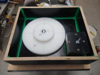
I use form ply for the mold, this has a surface on it nothing will stick to, it's often used for concrete slabs. Before pouring the whole surface is waxed with carnauba wax natural shoe polish and a few coats of hair spray.
All surfaces are machined flat. Then paint the surface with unwaxed resin which remains sticky, lay mat over and finish with waxed resin which I tint black, I usually use gelcoat but ran out. The plinth still requires a fair bit of filling and sanding to get it flat.
All surfaces are machined flat. Then paint the surface with unwaxed resin which remains sticky, lay mat over and finish with waxed resin which I tint black, I usually use gelcoat but ran out. The plinth still requires a fair bit of filling and sanding to get it flat.
Attachments
A question, which I hope will save me having to read all 177 pages of this thread:
I have a BBC sourced SP10 mk II which has this extra box SH10-C with a pcb marked SFDP10U-03. The leads from the SH10-C to the SP10 are inconveniently short. I would therefore like to eliminate the the SH10-C box.
Does anybody know how to do this?
I have a BBC sourced SP10 mk II which has this extra box SH10-C with a pcb marked SFDP10U-03. The leads from the SH10-C to the SP10 are inconveniently short. I would therefore like to eliminate the the SH10-C box.
Does anybody know how to do this?
I've read through this entire thread and have continually come back to reference it for various bits of technical info as I've 1) been working on refurbishing my buddy's recently-acquired SP-10 Mk2A drive unit, and 2) lusting after my own SP-10. Thanks to all for your invaluable inputs to the discussion here.
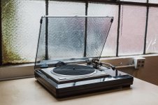
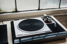
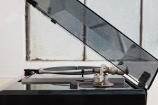
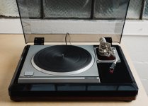
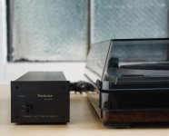
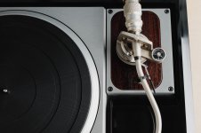
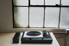
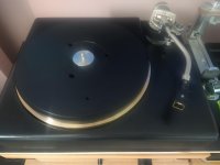
If you'll indulge a little bit of Technics porn to break up the technical discussion... attached are photos of the SL1000 mk2 (SP-10 mk2 + SH-10B3 + EPA-100) I acquired yesterday. I'm still having to pinch myself about actually getting my hands on this, as it is an *extremely* clean unit, at what was a very reasonable price, and was locally available. It came from the estate of the original owner (never saw any radio station duty), briefly into the hands of the seller, and then to me. I'm over the moon.
Supposedly, the seller's father (an electronics tech) did go through the service manual procedure for aligning the FG waveforms, but I will be getting inside the drive unit to verify for myself, after replacing the C2, C4, C6 caps per Dave Cawley's recommendations in this thread. Even though the speed on the strobe looks stable and accurate, the neon strobe lamp is a bit dim and flickering at times, indicating to me a problem with the 140V rail, so my first endeavor will be recapping the half-wave rectifier caps (and the other supply caps) while I'm at it, to see if that fixes it. Other than that, everything seems nearly perfect.
I'll run the deck with the "Obsidian" plinth for a while to get acclimated to its sonic character, while blue-skying about alternative custom plinth designs. The bentonite/resin and panzerholz constructions are definitely high on the list, but something with a suspension (a la Mitch Cotter, as described on Sound Fountain) also seems to have merit.
In any case, fun times are ahead, to be sure!
Attachments
Last edited:
Well done ! The strobe bulb often fails so as long as the strobe lines are steady don't worry.
Dave
Ah, good to know! So you suspect the strobe bulb vs the actual rail voltage then? It appears Acoustand offers a replacement neon bulb (I'm not really interested in going the LED route).
It will be easy to figure out, either way. I wouldn't have been surprised if the 140V caps are failing; I design electronics for spaceflight applications, and using a cap rated for 160V working voltage on a 140V rail doesn't qualify as adequate derating in my book!
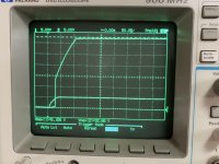
I've not yet opened up the power supply unit on my new deck, but I have measured the supply voltages for my buddy's SH-10EA unit, and everything is working fine, including the 140V. See the +5V and +32.5V rail turn-on behavior in the attached photo (didn't capture the 140V rail on the scope, but it measured fine on my Fluke DMM).
The SH-10EA can be hooked up to the Mk II drive unit with no issues, correct? If so, I could connect that power supply to my table to verify whether or not it's the supply. I don't remember seeing much of a difference between the schematics for the two power supply units. I'm not sure if the older supply had the crowbar for the 32V rail.
Attachments
Last edited:
EA will work fine on a MKII.
Thanks, JP - I looked at the schematics again and didn't see a reason not to, so I hooked up the EA supply from my buddy's turntable (which I had previously checked out on the scope/meter), and the strobe lamp was nice and stable - so it's a problem with the HV rectifier in this case.
I'll recap the power supply this weekend!
I have had a fault with the 140 rectifier ! But it's a simple circuit. And well done !
Dave
Indeed! Just a few components; should be an easy fix. I have a Mouser parts order on the way (had most everything I needed to refurb/recap the drive unit and supply unit except the HV caps and the Zeners), but I will be getting started on refurbing the supply this weekend.
")
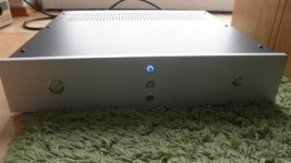
refurbished and repainted
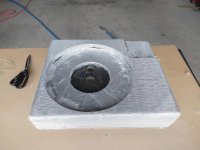
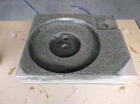
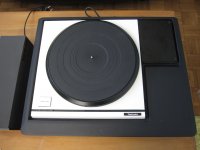
Hi, I am new in this forum. I am using Technisc SP 10 motor units for a long time in my home audio system. Building some plinth from Panzerholz for this units was always nice. Had a chance to get some plates of Panzerholz and use it for my DD turntbales as plinth material.
Never found better material. I also modify and service them on my own. My last one was in the original plinth but was completely refurbished and repainted.
Attachments

Hi, I am new in this forum. I am using Technisc SP 10 motor units for a long time in my home audio system. Building some plinth from Panzerholz for this units was always nice. Had a chance to get some plates of Panzerholz and use it for my DD turntbales as plinth material.
Never found better material. I also modify and service them on my own. My last one was in the original plinth but was completely refurbished and repainted.
Very nice builds there DD.
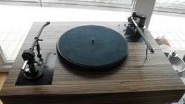
I too use an SP10 motor in a plinth separate from the electronics. The difference this makes is massive.
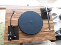
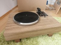
Yes this wa my first try. After this I am planing doing it also with an Exclusiev P3 and P10 unit. It seems to be a little easier with the Pioneer units. The SP10 made a big step forward. Mr. Kaneta did this first in the 70th years. I red his article and understand the point. The outsourced electronic is also much nicer and more just in time. I love the shaped look more than the original unit. This is only my opinion. The plinth with two tonearms made of Panzerholz is around 60kg. It looks very understatement and is realy heavy. It is a great material for turntable plinth.
Panzerholts or Permalli are great materials for plinths, it's unfortunate here in Australia Permalli is very expensive. I priced it for a plinth and was over $1000 just for the material.
I used resin/bentonite and this works extremely well too.
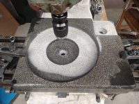
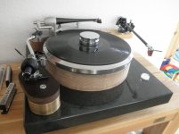
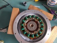
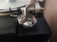
I have spent many hours on my SP10 setup to reduce micro vibrations that smear the sound.
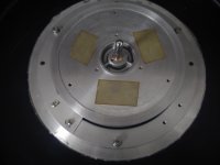
If you look carefully at the first pic you will notice I have re-drilled the motor mount for 3 bolts and there are M4 washers between the motor and the aluminium plate underneath to ensure there are only 3 contact points.
The motor housing has been damped with Blu Tack and if look carefully at the rotor you can see the brass insert. The motor spindle is now an interference press fit to reduce the wobble of the OEM glued in spindle.
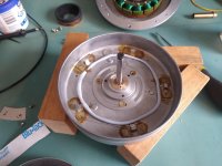
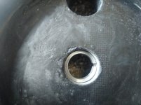
The next pic is the bearing housing collar inside the plinth to ensure the bearing is rigid. As the bearing housing goes down the collar spreads and locks the housing to the plinth.
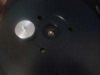
The platter is made from Gunmetal with 20mm Acetal (POM) bolted to the top and a secondary spindle is used as the motor spindle is below the top of the POM. The secondary spindle does not touch the motor spindle.
Lastly the EPA100 is heavily modified with a new SS CW that locks, viscous damping and a new more rigid mounting base.
The long and short of it is the sound is absolutely stunning.
.
I used resin/bentonite and this works extremely well too.
I have spent many hours on my SP10 setup to reduce micro vibrations that smear the sound.
If you look carefully at the first pic you will notice I have re-drilled the motor mount for 3 bolts and there are M4 washers between the motor and the aluminium plate underneath to ensure there are only 3 contact points.
The motor housing has been damped with Blu Tack and if look carefully at the rotor you can see the brass insert. The motor spindle is now an interference press fit to reduce the wobble of the OEM glued in spindle.
The next pic is the bearing housing collar inside the plinth to ensure the bearing is rigid. As the bearing housing goes down the collar spreads and locks the housing to the plinth.
The platter is made from Gunmetal with 20mm Acetal (POM) bolted to the top and a secondary spindle is used as the motor spindle is below the top of the POM. The secondary spindle does not touch the motor spindle.
Lastly the EPA100 is heavily modified with a new SS CW that locks, viscous damping and a new more rigid mounting base.
The long and short of it is the sound is absolutely stunning.
.
Attachments
-
 IMG_20210221_101438138.jpg343 KB · Views: 102
 -
 IMG_20210220_095030769.jpg900.8 KB · Views: 92
 -
 IMG_20210220_100401028.jpg965.7 KB · Views: 83
 -
 IMG_20210220_101038561.jpg979.3 KB · Views: 82
 -
 IMG_20210228_120423180.jpg472.2 KB · Views: 91
 -
 IMG_20210228_120411558.jpg263.5 KB · Views: 80
 -
 IMG_20210327_173439788.jpg403.8 KB · Views: 79
Your idea with the new POM platter is great. I also thought about replacing the upper aluminium platter. It is a lot of design and manufactoring only one or two platter. I think it will be much cheaper ordering more than 10 platters. May they are some SP10 user thinking about the same issue and will also use a POM upper platter on the original system. I am sure that this will also bring the SP10 a step forward. To design a make drawings of the upper platter should be not a big problem. Only the price in the oredering pieces will be the difference.
- Home
- Source & Line
- Analogue Source
- The Incredible Technics SP-10 Thread