The bentonite is granular (not powder!) and is often sold as Fines or Cattle Feed Supplement. I am not sure if this is the same as kitty litter.
For suitable pour conditions,
Bentonite is used as clumping kitty litter. This is what I bought.
Catsan Ultra | Pet Circle
Hi Bon
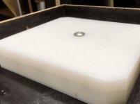
I cast top down, so top of the plinth is the bottom of the mold. I did this to keep the top as flat as possible. To flatten further I will put in on the mill and skim it with a 150mm face mill.
I used unwaxed isopthalic laminating resin. This stuff does not need sanding between layers, but is anaerobic so needs a lack of air to cure, you need to cover the exposed surfaces with clingfilm.
I have done a lot fiberglass laminating but this is the first time casting. Yep learning curve.
How do you find drilling and tapping the plinth for mounting hardware? Arm boards, feet etc
I don't know how well the material will take to milling. It might clog your tool and blunt it. I always putty up with a lightweight body filler and sand. It is time consuming.I cast top down, so top of the plinth is the bottom of the mold. I did this to keep the top as flat as possible. To flatten further I will put in on the mill and skim it with a 150mm face mill.
I have found 50 durometer sorbothane 50mm hemispheres as footers, to be very good supports. The first of my previous mold photos show corner mould inserts for recesses to locate the hemispheres. If you want to go for something prettier (but not necessarily superior), you could go for something like this.How do you find drilling and tapping the plinth for mounting hardware? Arm boards, feet etc
SORBOTHANE MEGA MOUNTS SPEAKER SUB TURNTABLE ANTI VIBRATION ISOLATION FEET PODS | eBay
but then you will have to epoxy M8 spike nutserts into the underneath.
I use SME tonearms with captive M3 nutserts epoxied into the underside of the tonearm recess, much less irritating to use than fiddling with nuts underneath.
As a general rule, I use stainless steel hardware, especially for the chassis bolts. Very early on, I discovered that hardened steel bolts through the plinth showed signs of corrosion along the shaft but not at the two ends, from which I conclude that the residual vapour from the resin is mildly corrosive of steel. It is good practice to properly seal and prime for this reason alone. There have been no issues.
I noticed your inserts are hard did you find with the lower % of catalyst there is less shrinkage in the plinth.
I've just bought another SP10 - 1 is never enough, so I'll need to cast another plinth. I'll make inserts this time and was wondering how you went with the rigid inserts and cracking.
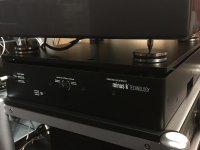
I have a set of ISOblack from Solid Tech which sit under a board with 3 cups on top and 12mm chrome balls. ISOblack provide vertical and ball horizontal isolation to about 3Hz.
I've just bought another SP10 - 1 is never enough, so I'll need to cast another plinth. I'll make inserts this time and was wondering how you went with the rigid inserts and cracking.
I have a set of ISOblack from Solid Tech which sit under a board with 3 cups on top and 12mm chrome balls. ISOblack provide vertical and ball horizontal isolation to about 3Hz.
I have found 50 durometer sorbothane 50mm hemispheres as footers, to be very good supports. The first of my previous mold photos show corner mould inserts for recesses to locate the hemispheres.
Have you compared 50 vs 70? BTW how hard it to drill a hole in that material?
Good questions. The inserts need to be material that is solid enough to survive the extraction process, and with a slippery surface to aid removal. My solution is the white polyethylene kitchen cutting board, which can be found from kitchen wholesalers in various thicknesses up to 25mm, and can be snugly screwed together in layers for the desired thickness. They are cut to size with the table saw, on a slight taper to aid removal from the casting. Each insert has a central threaded 3/8" through bolt that is pulled through a support block with a winding nut to gently extract the insert, minimising the risk of cast cracking. For the SP10 chassis insert, the bolt protrudes through the base of the mold.I noticed your inserts are hard did you find with the lower % of catalyst there is less shrinkage in the plinth.
I've just bought another SP10 - 1 is never enough, so I'll need to cast another plinth. I'll make inserts this time and was wondering how you went with the rigid inserts and cracking.
BTW the mold material is formply and liberal mold release is used.
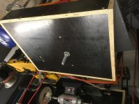
With my plinth depth, the base is about 25mm thick. I rejected an open base because a solid bottom plate significantly increases the torsional stiffness of the plinth. The resulting total mass of plinth+SP10+tonearm is around 40 kg, which is hard to find suitable isolation feet for.I have a set of ISOblack from Solid Tech which sit under a board with 3 cups on top and 12mm chrome balls. ISOblack provide vertical and ball horizontal isolation to about 3Hz.
I agree, 1 SP10 is never enough.
Attachments
I have only used the 50 Duro version. Might give the 70 a try next.Have you compared 50 vs 70?
I have found that drilling the bentonite resin creates significant heat. Makes sense, because the whole purpose of the composite material is high damping factor i.e. effectively convert mechanical vibration to heat. Drill bits lose the cutting ability far sooner than normally. For the larger holes for the tonearm cable and SP10 dc cable, I have capped tubular inserts (25mm pvc plumbing tube) that are press fit through the rear wall of the mold. When the cast is ready for removal, after unscrewing and removing the mold rear wall, the excess pipe can be trimmed off and a long 25mm spade bit drills through the imbedded cap to the tonearm recess and SP10 chassis recess. This saves drilling big holes in a difficult material.BTW how hard it to drill a hole in that material?
Bentonite and its uses
https://www.pjevans.com.au/wp-content/uploads/2018/05/709805uses.pdf
Here is some information on bentonite and its uses:
https://www.pjevans.com.au/wp-content/uploads/2018/05/709805uses.pdf
The resulting total mass of plinth+SP10+tonearm is around 40 kg, which is hard to find suitable isolation feet for.
Mistaken!
Isoacoustics Gaia 1 or Gaia 2; it is only essential to put your hand in your wallet!

I have put my hand much deeper into my wallet!Mistaken!
Isoacoustics Gaia 1 or Gaia 2; it is only essential to put your hand in your wallet!
https://www.minusk.com/documents/sp...ion_isolation_systems_antivibration_table.pdf
Attachments
My speakers go down to 20 Hz. Don't you ever wonder what is happening to your turntable when the concrete floor is shaking? I won't die wondering. All decisions are based on physics not fashion. Anyhow, I try to live up to my signature lineWow....do you reside in California above the S. Andrew fault maybe?
Don't you ever wonder what is happening to your turntable when the concrete floor is shaking?
not only the floor but also the air brings vibrations, how do you solve this other problem when it reaches the turntable and tonearm and especially the cartridge?
Mass!! 60 kg total suspended for the SP10R.not only the floor but also the air brings vibrations, how do you solve this other problem when it reaches the turntable and tonearm and especially the cartridge?
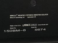
I have put my hand much deeper into my wallet!
https://www.minusk.com/documents/sp...ion_isolation_systems_antivibration_table.pdf
Good choice. It does suprise me that many people spend a fortune on a front end but poo poo something like a minus-k. SP-10 owners on the whole seem more open to the idea of a 'pro' vibration isolation solution. I wish I could afford one.
Another school of thought is that any such vibration is allowed to escape from the plinth to the mounting rack, shelf, whatever and that this support unit must be up to the purpose. Further, no one seems to have mentioned a 'drain' attached to the motor bearing.
[SEE: Albert Porter's plinth here:
<http://www.soundfountain.com/amb/sp10plinth.html>
For feet to a plinth, an approach I would strongly advise, use pure fine grain carbon blocks, say 2" cubic.
A bigger block can be centre drilled to a depth of about an inch and fitted snuggly to the bearing. This centre motor block should carry as much as possible of the plinth + unit weight whilst the three/four cubes can be shimmed for level.
Vibration not only travels very very fast through such carbon, but a percentage is turned to heat and thereby disappears as a 'minus' to sound quality. It is however important to use the fines grain from a dedicated carbon company.
The motor bearing 'drain' I view as an old wives tail, but happy to see some evidence of this to change my mind.
now for most of us the vibration is NOT from the turntable (untuned Lenco aside) but from the environment getting back in. For this the Minus-K is hard to beat at any price.
now for most of us the vibration is NOT from the turntable (untuned Lenco aside) but from the environment getting back in. For this the Minus-K is hard to beat at any price.
Further, no one seems to have mentioned a 'drain' attached to the motor bearing.
[SEE: Albert Porter's plinth here:
<http://www.soundfountain.com/amb/sp10plinth.html>
I've always looked for documentation with detailed photos of the solution, but I've never been able to understand what it consists of.
Even Artisan Fidelity on the new generation SP10R plinths has adopted this solution but does not show the solution.
Any of you have link with photo please?
The motor bearing 'drain' I view as an old wives tail, but happy to see some evidence of this to change my mind.
now for most of us the vibration is NOT from the turntable (untuned Lenco aside) but from the environment getting back in. For this the Minus-K is hard to beat at any price.
The SP10 has vanishingly low level of rumble. I have seen no before and after rumble measurements to verify this theory.
I tend to agree, anything that can let vibration out can also let vibration in. So if the deck is not well isolated the bearing drain could infact increase rumble.
One thought I did have was that the bearing drain stabilized the whole motor in the chassis.
Pitrus brings up a good question that I've thought about for years. My intent, when my SP-10 restoration comes to the front of the queue is to put a box around the plinth / table, etc., with the hinged parts being clear but fairly substantial. I don't see why one would make the world's most vibration-absorbing/dissipating plinth and then do nothing to control airborne (or airbourne...) noise.
- Home
- Source & Line
- Analogue Source
- The Incredible Technics SP-10 Thread