Circuit Mods for addition of stop start logic BBC Rp2/9
Thanks, my next move was to solve the stop start logic dilemma, it appears missing, but in reality it was always there minus some connections and debounce circuit. In fact there are two options either reuse the basic flip flop in IC 17 or use the redundant half of IC8 which has a spare JK flip flop.
I went for using IC8 and the JK flip flop. This is true to the Technics version with the logic already in service.
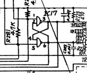
Photo 1 shows the original circuit.
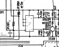
Photo 2 shows the new circuit redrawn with IC8 press ganged into service.
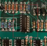
Photo 3 This shows how IC17 has been modified, I removed the IC and soldered a chip carrier to the board. I then snapped off legs 2,3,4,5 and 6 and replaced the IC in its socket. This renders the two unwanted gates inoperative.
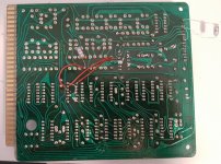
Photo 4 shows the wiring to connect IC8 and placement of C203. Additionally a link has to be connected from ST to VV to connect the clock input of IC8 Pin 1 to the stop/start switch. This is visible at the top right hand corner, also note the switch debounce capacitor connect across the stop/start switch to ground.
Finally the VV connection goes via the main connection board to the missing R166 resistor position on the control board. Essentially VV is really D1 and this can be traced to the controls socket on the main connection board and then via a single yellow wire from the controls socket/plug to R166. Totally remove the yellow wire by cutting it both ends. Then solder the correct resistor into R166 on the control card. Photos 5 and 6 show R166 pre and post mod.
I've yet to arrive at the correct values for the stop/start switch debounce RC combination. I will scope it with a decade box connected for both R and C. I started out with 56k and 0.1uF soldered in but reducing C to 0.001uF has got my in the ballpark, as I can now start and stop the turntable on most attempts.
All my controls work having reinstalled the switches and connecting the requisite wires from controls to the controls connection plug.
Its an efficient set of modifications as no tracks have to be cut or ICs dead bugged. That might change if the debounce can't be made to behave with the RC combo.
Thanks, my next move was to solve the stop start logic dilemma, it appears missing, but in reality it was always there minus some connections and debounce circuit. In fact there are two options either reuse the basic flip flop in IC 17 or use the redundant half of IC8 which has a spare JK flip flop.
I went for using IC8 and the JK flip flop. This is true to the Technics version with the logic already in service.
Photo 1 shows the original circuit.
Photo 2 shows the new circuit redrawn with IC8 press ganged into service.
Photo 3 This shows how IC17 has been modified, I removed the IC and soldered a chip carrier to the board. I then snapped off legs 2,3,4,5 and 6 and replaced the IC in its socket. This renders the two unwanted gates inoperative.
Photo 4 shows the wiring to connect IC8 and placement of C203. Additionally a link has to be connected from ST to VV to connect the clock input of IC8 Pin 1 to the stop/start switch. This is visible at the top right hand corner, also note the switch debounce capacitor connect across the stop/start switch to ground.
Finally the VV connection goes via the main connection board to the missing R166 resistor position on the control board. Essentially VV is really D1 and this can be traced to the controls socket on the main connection board and then via a single yellow wire from the controls socket/plug to R166. Totally remove the yellow wire by cutting it both ends. Then solder the correct resistor into R166 on the control card. Photos 5 and 6 show R166 pre and post mod.
I've yet to arrive at the correct values for the stop/start switch debounce RC combination. I will scope it with a decade box connected for both R and C. I started out with 56k and 0.1uF soldered in but reducing C to 0.001uF has got my in the ballpark, as I can now start and stop the turntable on most attempts.
All my controls work having reinstalled the switches and connecting the requisite wires from controls to the controls connection plug.
Its an efficient set of modifications as no tracks have to be cut or ICs dead bugged. That might change if the debounce can't be made to behave with the RC combo.
Attachments
-
 IC17 Before Mod.JPG48.1 KB · Views: 620
 -
 IC8 JK Stop Start Mod Edit.jpg86.5 KB · Views: 625
 -
 IC17 Mod Edit.jpg121.3 KB · Views: 619
 -
 Logic Board Rear Wiring Stop Start.jpg432 KB · Views: 622
 -
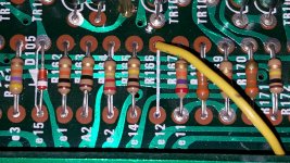 Control Board R166 Before Mod.jpg577 KB · Views: 605
 -
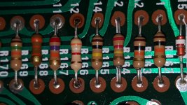 Control Board R166 After Mod.jpg437.5 KB · Views: 160
Last edited:
Dave,
Its one of those tasks where you sit and pore over all the diagrams for hours on end, making notes until it all clicks. Having all the different versions of the schematics helps a lot. Plus reading this thread has been very helpful and some of the things you mention on your own site have steered me in the right direction. Hats off to yourself and the other folks for sharing all the info.
Its one of those tasks where you sit and pore over all the diagrams for hours on end, making notes until it all clicks. Having all the different versions of the schematics helps a lot. Plus reading this thread has been very helpful and some of the things you mention on your own site have steered me in the right direction. Hats off to yourself and the other folks for sharing all the info.
Finally found time to hook up the newly received oscilloscope.
All time duration for 33.3, 45 and 78 rpm has been adjusted accordingly to spec. The platter turns quietly & smoothly in all 3 speeds mode.
But everytime i press STOP button, the platter would stopped and reverse in direction for at least half a revolution !
Can anyone point me in the right direction where to troubleshoot for this fault.
Thanks
But everytime i press STOP button, the platter would stopped and reverse in direction for at least half a revolution !
Are you operating it without the mechanical brake? Could be that it uses both mechanical and electronic (reverse drive) braking.
Reversing platter issue.
Hi,
Does your new scope have a storage function. If so you can you use it analyse the logic. If you wanted to you could scope the stop start button and then monitor various parts of the logic and motor control to try and get an idea of where your problem lies. I personally would start at the drive section of the motor and see what happens when you press stop. Then work back from there. If that doesn't produce any meaningful results you might have to follow the chain all the way from the stop start button.
You might need to rationalise the chain of command forward from the stop start drive transistors on the logic board.
Happy hunting.
Maybe I'm just confused or haven't been paying attention. It was my understanding that a fair number of people remove the break band for whatever audiophile reasons, yet I've never heard reports that these people had reversing platters when they hit 'stop'. It was my impression that the platter would just slow down and stop like most other turntables.
If the SP 10 motor control is anything like an SL-1200, there is a reverse signal sent by the motor control to stop the platter quickly. If things are way out of adjustment on a SL-1200 it is possible to cause the platter to spin backwards momentarily after the stop button is pressed. I suspect the SP 10 uses the same electronic braking method as well as having a brake band.
If this is the case, see if there is an adjustment possible. If not start looking for out of spec resistors and capacitors.
If this is the case, see if there is an adjustment possible. If not start looking for out of spec resistors and capacitors.
Found the problem !
It was the time delay RC capacitor C204. Stock value as stated in the service manual is 330uF 10v, this value can be tweak to suit individual taste, just like the brake adjustment on SL1200MK2, instead of adjusting the VR, u may have to choose and swap a suitable capacitor value.
I disable my brake band entirely, because no matter how i adjust the band, there is always some rubbing while the platter spins, now that its removed, it's dead silent while in operation. Now my platter stops immediately without the mechanical brake band assist.
Having an oscilloscope to do the PLL time base adjustment, it really improved my 78 rpm speed mode, the t/t used to chatter and vibrate so much as though the platter is out of balance. Now the 78rpm operation is so smooth, similar to 45 and 33.3 rpm.
Now next issue is the actual rotation speed of the platter, mine is 33.5 rpm even though the strobe light is showing perfect LOCK-ON.
To be continue...
Now next issue is the actual rotation speed of the platter, mine is 33.5 rpm even though the strobe light is showing perfect LOCK-ON.
To be continue...
They’re both from the same clock.
- Home
- Source & Line
- Analogue Source
- The Incredible Technics SP-10 Thread