You assume correctly. 13.5kg is right up there in weight. How did you decide on all that Aluminum?I assume you mean the platter in the pic above for the inverted bearing motor. With the rotor it's 13.5kg. Made from 6061 T6 aluminium and POMC.
Don
The platter was designed after calculating the sound energy traveling through the POM and Al. The thicknesses used are to spread the energy returning to the stylus. POMC also has better attenuation of energy than acrylic.
The Al is there to increase rigidity and POM has similar acoustic impedance to an LP, so energy created by the stylus in the groove passes easily into the POM.
If all goes well and I don't get side tracked I should have it up and running in a week or so.
With the platter resting on the bench and a stethoscope on the POM tapping the bench there is no sound in the platter so it has good isolation. Even tapping the Al the sound is well damped hardly a dull thud.
Here is a preview of my inverted bearing SP10mk2 motor. The platter not yet properly balanced, this will be done with the magnet and FG mounted in the rotor.
The platter is currently spinning on a 2mm SI3N4 ball inside the platter. There is currently NO sleeve so the platter is spinning balanced on the pivot point only. Once I have the platter balanced a very thin ring will be added in the rotor as a sleeve to prevent the platter tilting.
View attachment 1136122
Astonishing developments in this thread.
Good news, bad news.
I drilled the 38mm tone arm hole. Used an annular drill bit and mag drill. Worked perfectly. Dead nuts on location and a perfect hole mic'd at 38.11mm using a 38.1mm drill (1 1/2"). Whole different world using the right equipment. Thanks for the tip Bon. Pics attached.
Now the bad news. I totally screwed up the Tonearm elevation. I have to rework that part of the plinth. Top and bottom surfaces since I need to maintain appropriate material thickness for the tonearm mount. Then repaint it.
Don
If it's too low just add an aluminium spacer between the arm mount and plinth. I did this with my EPA-100 and it works fine
I used carbide router bits in the milling machine to rout the R/B plinth works well and the router bits are cheap.
My R/B plinth was 25mm thick where the tonearm mounted this allowed the EPA-100 to easily mount. The other option is to mount the tonearm to an aluminium plate and bolt the plate to the plinth.
My R/B plinth was 25mm thick where the tonearm mounted this allowed the EPA-100 to easily mount. The other option is to mount the tonearm to an aluminium plate and bolt the plate to the plinth.
@warrjon, re #2168
Warren, trying to make some decisions on the Panzerholz plinth. I have Questions regarding yours. All for understanding the reasons why.
1. You put an Al layer on the top and bottom of the plinth. Why?
2. You elevated the platter. Why? is the motor mounting ring directly on the Permali surface? If not why?
3. You have four potential TA mounting points.????
Thanks, trying to make as few mistakes as possible and get the best results I can.
Don
No problem Don.Warren, trying to make some decisions on the Panzerholz plinth. I have Questions regarding yours. All for understanding the reasons why.
1. You put an Al layer on the top and bottom of the plinth. Why?
2. You elevated the platter. Why? is the motor mounting ring directly on the Permali surface? If not why?
3. You have four potential TA mounting points.????
Thanks, trying to make as few mistakes as possible and get the best results I can.
Don
1. The 3mm Al plates top and bottom are there to increase rigidity and prevent the Permalli from ever warping.
2. After a lot of research and pontification on how sound waves travel in plinths I decided to raise the motor and arms off the plinth. This effectively increases the distance sound has to travel between the motor and arm base, it also has to go around corners. I did perform measurements between the R/B and Permalli plinths, the results were a significant decrease in acoustic feedback to the platter and tonearm mount from the plinth. The motor mount is on Al only the tonearms are directly on the Permalli, If I was doing this again I would NOT put the cutouts in the Al for the tonearm pods. Placing a stethoscope on the Permalli or Al I could hear no difference.
3. The plinth is designed to facilitate almost any tonearm including a linear tracker I'm working on.
Everything I do follows classical physics and good engineering principles. I'm not a mechanical engineer my gig is electronics, but engineering principals are universal.
The SP10mk2 has the potential to be a giant killing TT. what @Bon and I have done with remote motors and POM platters has improved the mk2 so significantly it would be difficult to top and any price.
The SP10mk2 has the potential to be a giant killing TT. what @Bon and I have done with remote motors and POM platters has improved the mk2 so significantly it would be difficult to top and any price.
Just thought I'd post an update to my inverted bearing motor.
After adding the retaining ring for the lower spindle I have significant vertical runout. I have struggled to get the pivot point perfectly concentric with the thrust line. It's 0.08mm out but this translates to 0.35mm vertical runout at the edge of the platter.
I have redesigned the pivot integral to the motor rotor, with the platter now separate. Previously the rotor was mounted to the underside of the platter and the pivot part of the platter.
@donhughes111
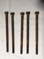
For peace of mind I use 304 stainless fastenings where possible. I found hardened steel bolts through resin/bento corroded over time.
I concluded the resin outgassing is corrosive. Since densified wood products like Panzerholz, Permali etc are resin infused, they may also be corrosive to hardened steel, although I have not seen such reported. Where the resin/bento is sealed with many coats of primer/paint/clearcoat I have seen nothing of concern. It is only the through holes into the raw material where I notice the problem. Nothing to report since using 304 stainless bolts/nuts/screws.
Here are 5 mkII bolts after about 5 years in a resin/bento plinth. The end threads and hex caps outside of the resin/bento are unaffected. The replacement 304 stainless hardware are still perfect.
Attachments
") Surprising how the steel was attacked by the plinth. Thanks.
Surprising how the steel was attacked by the plinth. Thanks.My Panzerholtz build is getting serious. The Panzerholtz arrived. It is 25mm B25. I haven't even started but I am nervous about the build. Really don't want to make a mistake.
I have two big questions to get started:
1. My plates are 400mm x 500mm CNC cut so a perfect edge and perfectly matched . What method would you suggest for glueing them together. I would like to be able to hold the edges and then get lots of pressure to press the plates together. I could vacuum bag it but don't know if it will work with clamps. Maybe I could pin it in place and then bag it? Pre drill it and then machine screw it together with the epoxy wet? Other?
2. Mounting the motor to the plinth. The simplest would be to elevate the motor with the mounting flange above the top surface (minimum of routing). But, that leaves a weird big gap between the platter bottom and the plinth. That gap could potentially could be closed with Al or PZ. Just don't know what works best. Trying to achieve good looks and good acoustics.
Thank you for your ideas.
Don
Hi Don,
My Aluminium motor pod is 220x25mm. It's drilled for 8 M6 coutersunk bolts and bolted directly to the Al/Permalli. The Pod could be made from Pz or you could even try plywood as it's removeable it can be replaced easily.
To lineup your Pz I would clamp them together and line up the edges then drill 2 dowel holes through the bottom layer into the top bit this way you'll ensure they're lined up, they can then be glued up with no chance of movement.
The bottom of my platter is 30mm above the plinth. If you don't like this the only was would be to increase the thickness of the plinth to cover the bottom of the platter. I like the naked look and exposed platter kind of looks like nothing else and it works.
- Home
- Source & Line
- Analogue Source
- The Incredible Technics SP-10 Thread