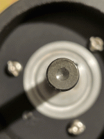
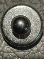
In the spirit of data collection, I inspected the thrust pad and ball from a second mkII motor. The motor dates from 1984 so is 5 years younger than the previous one. The ball is original. The Torlon thrust pad was installed 5 years ago at the same time as the one previously reported. It has a similar amount of use. The pad wear size is similar to the previous one but does not show the swirl pattern and I can find no evidence of wear on the ball. The 2 samples of the mkII were acquired at different times and will have a different use and maintenance history. The evidence thus far appears to be inconclusive on the question of ball wear.Honestly I don't see any wear pattern anywhere on that ball. And it is the one I removed from the TT. The largest problem I had getting a photograph of that ball were the reflections. They masked everything.
-Steve
What does concern me is the amount of wear of the Torlon thrust pads. I was accepting of the results from previous investigations
https://www.theanalogdept.com/sp10_brg.htm
that showed minimal wear pattern size increase at the 1 week mark, as indicative of a long lasting thrust bearing under normal use and maintenance. The size of the Torlon wear scar on both of the mkII thrust bearings makes me question this assumption.
Attachments
The wear pattern in the torlon (4301?) does appear smooth unlike what we have seen in oem pads. But the crater is larger than I expected. 5 years.
Torlon 4203 exhibited a more rigid, less elastic property in my experience but would that result in a smaller wear crater under the same conditions over the same time...? No doubt lube grade plays into this. I was using 20 wt. turbine oil in mine.
One idea I get, based on looking at the plethora of chewed up thrust caps and apparent shaft wear on this model in these threads is that the SP10 mkII bearing really needs frequent maintenance.
-Steve
https://www.theanalogdept.com/sp10_brg.htm
I've just been looking through this page and one thing that struck me was the difference between the newly installed cap and 1 week later especially 20-100Hz. The newly installed cap shows almost universally 12dB lower than 1 week later.
Got me thinking that a hard thrust pad might offer lower noise. Sapphire running on SI3N4
What was the maintenance procedure and interval since the thrust pad was installed? Extra weight on the platter? Any pictures of the amount of ground-away material?In the spirit of data collection, I inspected the thrust pad and ball from a second mkII motor. The motor dates from 1984 so is 5 years younger than the previous one. The ball is original. The Torlon thrust pad was installed 5 years ago at the same time as the one previously reported. It has a similar amount of use. The pad wear size is similar to the previous one but does not show the swirl pattern and I can find no evidence of wear on the ball. The 2 samples of the mkII were acquired at different times and will have a different use and maintenance history. The evidence thus far appears to be inconclusive on the question of ball wear.
What does concern me is the amount of wear of the Torlon thrust pads. I was accepting of the results from previous investigations
https://www.theanalogdept.com/sp10_brg.htm
that showed minimal wear pattern size increase at the 1 week mark, as indicative of a long lasting thrust bearing under normal use and maintenance. The size of the Torlon wear scar on both of the mkII thrust bearings makes me question this assumption.
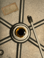
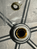
The motor in #2121 came from a stock mkII with oem platter. It has had light use and regular lubrication since the oem thrust pad was replaced with Torlon 5 years ago. Fortunately, the bearing was sitting untouched since I recently removed the ball for inspection. I cleaned the ball and thrust pad to take the pictures in #2121 and they were dirty but not what I would call caked. The bearing was sitting overnight on a small zip-loc bag to catch any oil leak. It can be seen that the residue is dirty (with Torlon residue?). The journal looked reasonably clean and unworn but it needs proper measuring tools to confirm this. Looking through the bearing towards a light source does not show anything concerning.What was the maintenance procedure and interval since the thrust pad was installed? Extra weight on the platter? Any pictures of the amount of ground-away material?
The cotton-bud was used to clean the journal. The bottom of the bore is still wet with dirty oil. The bottom of screw cap has a fair amount of clean oil which must have made it past the bearing ball. It indicates that Torlon residue did not bypass the ball.
Attachments
Last edited:
I found my original posts in this same thread from 5 years ago when I replaced five SP10 mkII thrust bearings with Torlon from Woodsong Audio. The project was inspired by post #878 from 6L6 showing the condition of his bearing before replacement. I have replaced a few more since but it is only recently that I have re-examined some of the bearings. Others of the mkII are no longer in my possession. Posts #893, 895, 904, 914, 914, 915 show details of the original bearings at time of replacement.
https://www.diyaudio.com/community/threads/the-incredible-technics-sp-10-thread.261735/page-45
https://www.diyaudio.com/community/threads/the-incredible-technics-sp-10-thread.261735/page-46
There are some interesting comments from members. This together with my recent posts, is a visual record of the progression of the wear over the 5 year period. Although I did not remove and inspect the balls, nearly every image of the 5 thrust pads show the typical bulls-eye pattern indicating ball wear. The recent re-examination of the 2 replaced thrust bearings show a similar amount of wear to the originals at the time of replacement.
What I take from this, is that the Torlon is not necessarily superior to the original or other tested bearing materials. More importantly for me is the conclusion that the bearing requires a regular inspection, maintenance and replacement regime to preserve the performance of the motor unit. A Torlon replacement is not a panacea for long term peace-of-mind.
Since the mkII was primarily produced for the professional audio market, I would expect that radio stations, recording studios, disc cutting facilities and the like, would have some kind of maintenance schedule but I have never seen any such recommendation in the service manual.
More importantly for me is the conclusion that the bearing requires a regular inspection, maintenance and replacement regime to preserve the performance of the motor unit. A Torlon replacement is not a panacea for long term peace-of-mind.
I do not entirely agree; the ball and the original thrust bearing have withstood decades (40 years and even more) to abuse and continued use in radio stations and little to no maintenance, consequently I deduce that the wear was ascertained by the owners who have them purchased from disused radios. New materials with which the current thrust pads are composed have not reached a long-term reliability because tested for a short time this is my opinion. In fact, I wanted to keep all the original thrust pads of the different Sp10 that I own.
From the thrust pads I have replaced in SP10's that came from smaller broadcast environments, all of them had significant wear on pad and ball. Larger organisations like the BBC would have preventative maintenance schedules.
These pics are typical of the ones I have seen. In fact the journal in this one is so badly damaged that after pads/ball replacement you can hear the bearing when the platter is spun. There is large score marks in the sleeve and on spindle, so the sleeve and spindle need to be replaced.
No longevity testing has been performed on the Torlon replacement pads. I have machined Vesconite and POM pads that Bon is going to install along with a now Torlon pad into 3 SP10's and run them continuously for a couple of weeks then measure each pad for wear.


.jpeg")
Congratulation!
Can I ask for more detail about the connections?
I broke my coil wires during disassembly. So I got no way to find out how it is connected.
I see your top coil is RED and the bottom coil is GOLD in color. So when you mentioned both coils connected in parallel.... meaning the start of the red coil wire connected to the start of the gold coil wire, and the end of the red coil to the end of the gold coil? Therefore these 2 connections will be the final output of the FG .
However, there is a pcb tab that is soldered with 2 coil wires and not connected to anything else. May i know what is this connection? I am a bit confused.
Thanks
@mdlover
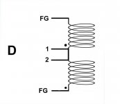
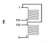
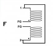
which of these links of yours would be correct image D or F?
I restored and connected a coil several years ago and it worked but I no longer remember if the small wires of the coils need to be soldered to the pcb with a logical arrangement in the two side pads or if it makes no difference if they are soldered reversed.
Both those coils are connected in the same polarity and would make no difference E in my drawing is different@mdlover
which of these links of yours would be correct image D or F?
I restored and connected a coil several years ago and it worked but I no longer remember if the small wires of the coils need to be soldered to the pcb with a logical arrangement in the two side pads or if it makes no difference if they are soldered reversed.
View attachment 1100176 View attachment 1100175
Unfortunately it's so long ago I rewound mine I can't remember which polarity is correct.
Attachments
I just did the above connections.oops, sorry my bad.
They should be connected in series instead.
The start of both coils are connected together and the end of each coils being the FG output.
Hope this helps.
The speed of the platter no longer spins out of control, but it hovers around 60-70 'ish rpm.
Can feel a bit of jerkiness on the plinth. It's like the circuit tries to catch or latch on to control the speed of the platter.
The next step is to adjust the timing spec with my scope, hope it turns up well.
- Home
- Source & Line
- Analogue Source
- The Incredible Technics SP-10 Thread