I own a tube preamp which has a phono stage. The phono stage has 2 sections, MM section which is tubes based, preceded by MC section which is JFET based. There is only one phono input in the preamp, intended to be used with only MC cartridges.
There was a fire in my house, during which the temperature in my living room was enormous (though I didn't measure it). However, since the fire the phono input has very loud 'cracking' noises, most probably caused by JFETs being damaged by the very high temperatures during the fire. With such a noise, the phono input is unusable, so I need to replace some JFETs, possibly all of them.
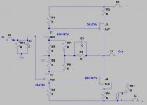
The simplified schematic of the JFET MC pre for one channel is attached.
On each channel there is a pair of 2SK147V N-JFET devices and a pair of 2SJ72V P-JFET devices.
What I have on hand is few dozens of 2SK170V, few dozens of 2SK170BL and few dozens of 2SJ74BL.
In addition to what I have, I can purchase few LSK74C JFETs, though I may encounter a problem with matching their Idss to the Idss of their existing adjacent N-JFET devices, so I may need to purchase a very large amount of those, which I cannot afford.
This is my debate and questions:
1. As for matching Idss, do I need to match only J1 to J2 and J3 to J4, or do I need to match all 4?
2. In case I need to replace only some JFETs, is it better to replace only the damaged ones, or is it better to replace all of them?
3. In case I need to replace J1 and/or J4, I guess I'd better replace them with 2SK170V(s). Am I correct?
4. In case I need to replace J2 and/or J3, basically I have 2 options. Option 1 is to replace each one of them with 2x 2SJ74BL in parallel; option 2 is to replace each one with LSK74C. Which option is preferred (when I cannot afford purchasing many LSK74C devices)?
5. In case I need to replace both J1+J2, and/or J3+J4, assuming that for P-JFET devices I'll replace each existing device with 2x 2SJ74BL in parallel, is it still better to use 2SK170V devices, or is it better to replace each existing 2SK147V with 2x 2SK170BL?
There was a fire in my house, during which the temperature in my living room was enormous (though I didn't measure it). However, since the fire the phono input has very loud 'cracking' noises, most probably caused by JFETs being damaged by the very high temperatures during the fire. With such a noise, the phono input is unusable, so I need to replace some JFETs, possibly all of them.
The simplified schematic of the JFET MC pre for one channel is attached.
On each channel there is a pair of 2SK147V N-JFET devices and a pair of 2SJ72V P-JFET devices.
What I have on hand is few dozens of 2SK170V, few dozens of 2SK170BL and few dozens of 2SJ74BL.
In addition to what I have, I can purchase few LSK74C JFETs, though I may encounter a problem with matching their Idss to the Idss of their existing adjacent N-JFET devices, so I may need to purchase a very large amount of those, which I cannot afford.
This is my debate and questions:
1. As for matching Idss, do I need to match only J1 to J2 and J3 to J4, or do I need to match all 4?
2. In case I need to replace only some JFETs, is it better to replace only the damaged ones, or is it better to replace all of them?
3. In case I need to replace J1 and/or J4, I guess I'd better replace them with 2SK170V(s). Am I correct?
4. In case I need to replace J2 and/or J3, basically I have 2 options. Option 1 is to replace each one of them with 2x 2SJ74BL in parallel; option 2 is to replace each one with LSK74C. Which option is preferred (when I cannot afford purchasing many LSK74C devices)?
5. In case I need to replace both J1+J2, and/or J3+J4, assuming that for P-JFET devices I'll replace each existing device with 2x 2SJ74BL in parallel, is it still better to use 2SK170V devices, or is it better to replace each existing 2SK147V with 2x 2SK170BL?
Attachments
1 . J1 to J2 , J3 to J4
2. replace also matching mate , if you can't find mate to survived one
3. it will work with BLs too , higher range , please ; though , it would be better that you included resistor values and some measurements
4. read #3 . think in verticals ..... why asking for horizontal "pairs" , when they aren't that
5. read #3 , again . values and voltages ; I can bet that BLs will work pretty much the same
1 . J1 to J2 , J3 to J4
2. replace also matching mate , if you can't find mate to survived one
3. it will work with BLs too , higher range , please ; though , it would be better that you included resistor values and some measurements
4. read #3 . think in verticals ..... why asking for horizontal "pairs" , when they aren't that
5. read #3 , again . values and voltages ; I can bet that BLs will work pretty much the same
Hi,
Thank you very much.
Please elaborate on your reply #3, what resistor to add where and what to measure?
Also, when replacing with 2x 2SK170BL and 2x 2SJ74BL, do I need to match the Idss of all 4, or only the sum Idss of one parallel pair to the sum Idss of the adjacent parallel pair?
Last edited:
Since the transconductance parameter for N and P devices is very different matching Idss for N and P does not really get you what you want. You want to achieve matched forward gain symmetry in the top vs bottom half and hopefully still have very low offset. It is in fact entirely possible that the right four unmatched devices achieve that. If you think about it there are 4 free parameters and only two things to get right, symmetry and offset. I would start with the easy part use matched pairs of N and P and select the Idss range of one or the other that gives the lowest offset and symmetry (even harmonics). This all depends on the values of the resistors and the gain of each stage.
If you had all the resistor values a simple sim in LTSPICE could give Idss ratios for N and P that fit the parts that you have.
If you post the values maybe we can help you out. My model files have the "beta" (transconductance parameter) for the SJ74 at about 1.4X the SK170 so matching all 4 for Idss will guarantee the wrong answer. Running at the same current N vs P will have a different gm.
Last edited:
I asked for resistor values in your schematic , and PSU voltage
- Idss of all 4 , unfortunately
Hi,
Thank you.
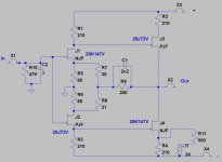
Updated schematic with resistors values is attached.
Voltages reading will be added later on.
Attachments
Last edited:
Ac and DC matching is what you want to find. Not easy but since you only need one circuit for your own system, it is do-able. a 'beta' ratio difference of 1.4 isn't toooo bad. On a bell curve of beta distribution and with a large enough lot of them, you can find a match. .... you will find some from the low side and some on the high side gets you a match.
Another way is to build this simple exact circuit which you will use them in and with sockets and plug in fets until you get best results (lowest thd and dc offset). Start with just the input pair.
There may be other suitable fets which have a closer ratio but you have what you have to work with. Good luck and hope you are quickly enjoying music again.
THx-RNMarsh
Last edited:
Since the transconductance parameter for N and P devices is very different matching Idss for N and P does not really get you what you want. You want to achieve matched forward gain symmetry in the top vs bottom half and hopefully still have very low offset. It is in fact entirely possible that the right four unmatched devices achieve that. If you think about it there are 4 free parameters and only two things to get right, symmetry and offset. I would start with the easy part use matched pairs of N and P and select the Idss range of one or the other that gives the lowest offset and symmetry (even harmonics). This all depends on the values of the resistors and the gain of each stage.
If you had all the resistor values a simple sim in LTSPICE could give Idss ratios for N and P that fit the parts that you have.
If you post the values maybe we can help you out. My model files have the "beta" (transconductance parameter) for the SJ74 at about 1.4X the SK170 so matching all 4 for Idss will guarantee the wrong answer. Running at the same current N vs P will have a different gm.
Hi Scot,
Thank you very much.
Please see my previous reply for updated schematic with resistors values.
Voltages reading will be added later on.
Few questions:
1. I need reliable spice models for 2SK170 and 2SJ74. Can you please post them?
2a. I have no clue about neither how to get the forward gain using LTSpice, nor how to calculate it. How do I get it, or calculate it?
2b. Can the gm be adjusted by different values of the source resistors and/or different values of load resistors?
3a. I assume that by 'symmetry' you mean DC offset. Am I correct here?
3b. As for the output DC offset, it seems to me that the 2K trimpot takes care of it. Am I correct here?
3c. If "yes" to both above questions, do I need to take care only about matching the forward gain in each arm, or still for both forward gain and DC offset?
All further assistance will be appreciated.
Ac and DC matching is what you want to find. Not easy but since you only need one circuit for your own system, it is do-able. a 'beta' ratio difference of 1.4 isn't toooo bad. On a bell curve of beta distribution and with a large enough lot of them, you can find a match. .... you will find some from the low side and some on the high side gets you a match.
Another way is to build this simple exact circuit which you will use them in and with sockets and plug in fets until you get best results (lowest thd and dc offset). Start with just the input pair.
There may be other suitable fets which have a closer ratio but you have what you have to work with. Good luck and hope you are quickly enjoying music again.
THx-RNMarsh
Hi Richard,
Thank you very much.
I have about 100 of each 2SK170BL and 2SJ74BL plus 50x 2SK170V, so it may do with the BL parts I have.
1. How do I measure, or calculate, the beta?
2. When in each arm (left and right sides, or input arm and output arm) there are 2x 2SK170BL in parallel and 2x 2SJ74BL in parallel, do I need to match the beta of all 4, or only match the total beta of the upper side in the arm (N devices) to the total beta of the lower side of the arm (P devices)?
3. As for DC offset at the output, can it be adjusted by selecting R7 and R8 values? If yes, I can start with a trimpot, later replacing it with fixed resistor(s).
Joshua, there are several 'suspect caps' that could have been damaged:C1 and C2 in your schematic should be checked by just lifting one lead into the air and seeing if the problem seems to disappear. The electrolytic caps in the power supply buffer are also very suspect. Personally, I doubt that you have an actually broken jfet. Let's get down to what is wrong, before speculating what to change.
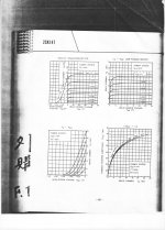
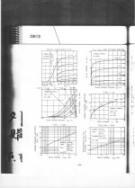
Included is a really 'clean' pdf of the 2SK170
Included is a really 'clean' pdf of the 2SK170
Attachments
Matching Beta is not real. Match Idss. This is why you need 2 paralleled devices to match Idss. It would be better to replace both complementary parts that are damaged, to match the Beta better. The DC offset adjust is already there on the card.
Hi John,
Thank you very much.
John is right to suggest checking other parts first. The transistors may be OK and either caps or even resistors could be distressed. The first art to check would be the trim pot. its exposed to air and can easily corrode in heat and polluted air and be come dodgy in its contact. Also the PCB may have stuff from the smoke on it. Clean the board with isopropyl and check it.
That circuit would be a real bear to mass produce with the complex matching required to make it work. If you match IDSS and the IDSS is close to the operating point for all the parts it may work. Not an easy way to get yield. Tweaking models to have a specific IDSS is beyond me. All the models for the Toshiba parts are reverse engineered models so they may not be that close to real parts.
That circuit would be a real bear to mass produce with the complex matching required to make it work. If you match IDSS and the IDSS is close to the operating point for all the parts it may work. Not an easy way to get yield. Tweaking models to have a specific IDSS is beyond me. All the models for the Toshiba parts are reverse engineered models so they may not be that close to real parts.
Joshua, please check the aluminum caps in the power supply buffer first, before changing the parts.
Thanks, John,
All electrolytic capacitors are on order, both all PSU caps, all MC pre supply filtering caps and tubes cathodes bypass caps, since it's a 20 years amp. With the capacitors I also ordered fast recovery diodes for all 3 parts of the PSU.
They should be here within about a week.
It's my initial intention to locate the faulty FETs only after replacing all electrolytic capacitors.
Joshua, compressed air will replace 'freeze spray' in many cases.
I already got freeze aerosol.
Right now I'm going through my (highly messed up) storage to locate all the FETs I have there.
John is right to suggest checking other parts first. The transistors may be OK and either caps or even resistors could be distressed. The first art to check would be the trim pot. its exposed to air and can easily corrode in heat and polluted air and be come dodgy in its contact. Also the PCB may have stuff from the smoke on it. Clean the board with isopropyl and check it.
That circuit would be a real bear to mass produce with the complex matching required to make it work. If you match IDSS and the IDSS is close to the operating point for all the parts it may work. Not an easy way to get yield. Tweaking models to have a specific IDSS is beyond me. All the models for the Toshiba parts are reverse engineered models so they may not be that close to real parts.
Hi Demian,
Thank you.
Off course the PCBs will be cleaned first, this goes without saying for me, being a (retired) repair technician for so many years.
With ohmmeter, both trimpots measure very closely and reasonably (about 500 Ohm each), so it looks they are okay. Anyhow, measuring the DC offset at the output would tell about the condition of the trimpots.
As for spice simulations, I'm skipping it willingly and gladly, since I'm well aware of the discrepancies between Toshiba JFET models and the real parts.
All testing will be done after replacing all the electrolytic capacitors and replacing a MOSFET with broken leads.
Note the polystyrene caps.
Thanks, John.
All polystyrene caps are ordered as well.
- Status
- This old topic is closed. If you want to reopen this topic, contact a moderator using the "Report Post" button.
- Home
- Source & Line
- Analogue Source
- JFETs replacing and matching questions