EO Phono Simulation
I've been reading various forums looking for tube phono preamps (many LCRs) and spent the past few days going over the 2 phono preamps that SY's presented. I got the LA articles and read those too.
I like to try and sim circuits before building, so I thought I'd share what I've sim'd of the EO phono preamp. The sim is in LTSpice, a free download. I placed ".models" on the sim, so no extraneous include files are needed. (I read in one comment that SY doesn't care for sims, so I hope my upload is not disliked too much.)
I was not able to locate models (or at least symbols that allowed me load the model data) for the selected output mosfets. I substituted ones that seemed close (but what do I know; so please change).
Another change I made (these are noted in a text on the sim), is placing 1K resistors in the anodes rather than 10K or jumpering them, so I could easily monitor the current. (I use a Mac, and on a PC I can place current monitors, but my Mac only lets me place voltage.) And speaking of this, I indicated power dissipations on the sim.
I also sim'd the RIAA to get as flat a response from the inverse RIAA input as possible. I've entered those new values on the sim, so change back as you see fit.
One thing I noticed is a rise in high freq over 20kHz. The only way I could tame it was to add 330pF about the output mosfets. I don't know if this problem is a bad sim issue (an artifact of the wrong mosfet model, etc). So please remove or adjust as someone more knowledgable than me suggests.
Finally, I ran THD for input voltages varying from 0.01 to 300mV. These are presented in a comment table on the sim. (You can run sine wave, freq respon or THD yourself by unhiding or hiding instructions with ";") BTW, I up'd the current to 3.5mA and saw an modest increase in THD. so 2.5mA looks good. Monitoring of these values was done on one output leg, but input signal is on both legs.
Attachments
Yeah, mine is entirely based on the V8 article. I did not use buffers between the stages, but did include them on the outputs.
Other than the obvious issue with the second RIAA filter in the PDF, and the grid resistors, the primary difference between the PDF and the V8 article seems to be the values of the CCS resistors. Since these seem to be working fine as is, and the currents seem to be at about the right overall level (2.5 mA), I am inclined to leave it as is.
I am also curious about the purpose of the grid resistors. The grid currents are (presumably) rather low, and it would seem that all the resistors would do is add a noise source. SY confirms this in V7.
"The gain of each of the pFET source followers is extremely close to unity, since the load impedance is high (the grid load, nearly infinite, in parallel with the looking-in impedance at the tube cathode which is approximately the current source impedance divided by 1 + mu, on the order of several megohms)." (V7, Page 77)
Seems that a 100 ohm resistor in series with a 1M Ohm impedance would not be noticeable.
Unless there is some compelling reason I am missing, I am also not inclined to tear up my PCB to add these.
Your thoughts?
I went and re-read SY's discussion (V7) about the SYclotron topology. I am not familiar with the "biological amplifiers" he refers to, and he didn't provide much of a detailed explanation about how this topology works, only that it provides good CMR and low input capacitance.
After thinking on this a bit, I see that as the input signal rises, the P-FET transconductance will decrease (depletion mode). So this means as the signal on one arm of the pair rises, the signal on the cathode of that tube will rise, thereby reducing the current in the tube. Meanwhile the transconductance of the other P-FET will increase, causing the signal level at the cathode of the other tube to fall, thereby increasing the current flow. This is normal Diff pair action, other than being driven by the plate side CCS's as opposed to a common drain side CCS as in a typical diff pair (I suppose that is one reason that matching the CCS's is so critical here).
For balance inputs then, the grid potential of one tube will fall(because the opposing P-FET is turning on, thereby reducing the source potential), as the collector potential rises because the same side P-FET is turning off (thereby raising the source (and cathode) potential. Thus in this mode, the grid-cathode potential decreases, causing the tube to conduct (thereby producing gain in that arm). The same thing occurs in the other arm on the other half cycle.
Now for common mode signals, a rising signal will cause the transconductance of both P-FETS to decrease, thereby raising the signal levels at the sources. These are fed through to the other tube grids, causing the grid potentials to rise, except the cathode potentials are also rising, so the result is no increase in tube conduction, and no gain.
Interesting!
Scott
I like to try and sim circuits before building, so I thought I'd share what I've sim'd of the EO phono preamp. The sim is in LTSpice, a free download. I placed ".models" on the sim, so no extraneous include files are needed. (I read in one comment that SY doesn't care for sims, so I hope my upload is not disliked too much.)
Hi rl,
I don't know if you have heard, but SY is taking a vacation from DIYaudio, so he won't be around to respond. Jackinnj, the OP for this thread, has done some interesting sim work on the circuit and SY shared some real world testing results in the articles, so you should have something good to compare to.
As for me, I stink at simulation, so I'll leave it to more knowledgeable folks to respond.
Seems that a 100 ohm resistor in series with a 1M Ohm impedance would not be noticeable.
Unless there is some compelling reason I am missing, I am also not inclined to tear up my PCB to add these.
I would be totally guessing, but if I were to guess, I think SY put the grid resistors in as standard practice, maybe to keep a little damping against oscillation. Anyway, I think you are right that any difference won't be major as long as everything else is working. I wouldn't tear up your pcb unless somebody comes along and explains.
Jac
Set up the other channel board today. Went super fast. Other than the tube sockets being bad..(The tubes were very tight in the sockets, so I had used a tweezer to open them up.. but went too far, and then the tube contacts were flaky.. so I changed them out..)..the preamp works great!
Spent the afternoon making cables, and hooking up connectors so I can put the boards in the chassis.
Here's the power supply all buttoned up.
Should be ready to play on Sunday!
Cheers,
Scott
Spent the afternoon making cables, and hooking up connectors so I can put the boards in the chassis.
Here's the power supply all buttoned up.
Should be ready to play on Sunday!
Cheers,
Scott
Last edited:
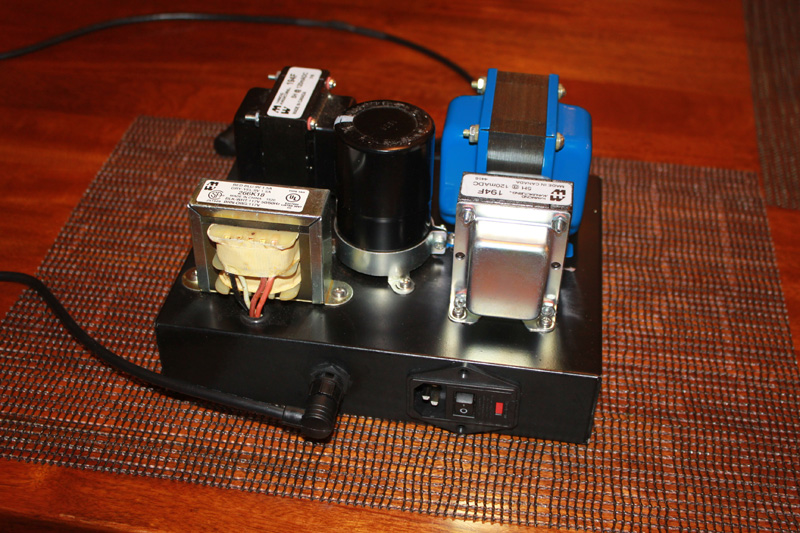
Here's the power supply all buttoned up.
Should be ready to play on Sunday!
Very nice. From the blue trafo, I'm guessing that you have an interesting collection of iron to choose from. And the big old cap standing upside down is really a cool idea.
I hope you enjoy Sunday.
Jac
The blue one is from Edcor. It was a special order. It has 120/CT/120 and 12/CT/12 windings.
I am, however, slightly confused. I scaled the primary for this from the HMN power supply, and it works, but I am not sure why it works.. Based on my understanding of rectifier theory, the DC output of a full wave rectifier should be 0.637Vp, where Vp is the peak value of the half cycle. For 120 Vrms, the peak should be ~171 volts, and this should, theoretically produce a DC level of only 109 volts (=171*.637). However, the circuit produces about 169 volts. I am not sure if the theory is using an un filtered assumption and, with no load, the choke and capacitor are simply filling in the low spots, or I don't understand the theory I have been reading.
I suppose, with no load, the cap could just hold the signal at the peak value all the time, but as soon as any energy was drawn off it, conservation of energy would tell us that the average value would need to fall to at least somewhere around RMS. Yet, in operation, the plate supply stays clean at 125 volts...so if load reduces the output of the raw supply, it isn't by much!
With this current setup I am putting 169 volts into the 125 volt regulators, and they seem to be OK. The 12 volt winding generates 17 volts DC, and that seems to be OK for the -15 volt regulator.. maybe a little shy on headroom there... but in both cases had I followed theory, I would have chosen a larger secondary voltage. So, I dodged a bullet there, but not sure why..
Yeah, the cap is pretty cool. Big sucker! 470 uF at 400 volts! I got it for the HMN, so it is over sized for this application.
The blue one is from Edcor. It was a special order. It has 120/CT/120 and 12/CT/12 windings.
I am, however, slightly confused. I scaled the primary for this from the HMN power supply, and it works, but I am not sure why it works.. Based on my understanding of rectifier theory, the DC output of a full wave rectifier should be 0.637Vp, where Vp is the peak value of the half cycle. For 120 Vrms, the peak should be ~171 volts, and this should, theoretically produce a DC level of only 109 volts (=171*.637). However, the circuit produces about 169 volts. I am not sure if the theory is using an un filtered assumption and, with no load, the choke and capacitor are simply filling in the low spots, or I don't understand the theory I have been reading.
My guess is that the low current allows the supply to fall less from the peak, as you say. SY, who generally doesn't use simulation, does admit that the Duncan PSU Designer 2 does a nice job of simulating power supply. Don't know if you've tried it. It's free.
PSUD2
I have found it pretty useful, but I often don't have enough information about a transformer to accurately put it in SPU D2.
Anyway, as long as it's working, your golden.
Jac
The diyAudio store is currently selling matched quads (+/- .1mA Idss) of the LSJ74B pFets used with this project. I went ahead and purchased a couple sets of matched quads. Am I correct in understanding I still need to sort within these matched quads for matched GM?
Edit: it appears I found my answer in one of my old posts from 3 years ago:
https://www.diyaudio.com/forums/analogue-source/256062-equal-opportunity-mm-pre-30.html#post4940515
Edit: it appears I found my answer in one of my old posts from 3 years ago:
https://www.diyaudio.com/forums/analogue-source/256062-equal-opportunity-mm-pre-30.html#post4940515
Last edited:
I hope you do go ahead with the project. I admit, its been long enough that I don't remember many of the details, but I continue to enjoy the sound of the Equal Opportunity pre. As I have upgraded my analog front end and further improved the rest of my system, the Eq Opp has not limited the sound at all. I did build mine following the Linear Audio article and the discussion here, so if you do something different, YRMV.
I appreciate the encouragement but to be honest, even if I were to have this project completed tomorrow I would still be unable to integrate into my system in its current configuration (disc player & home theater receiver). This project is one of a handful where I’m biding my time amassing parts until we are able to relocate from our rental to a larger space with an electrical system that’s actually wired to code.
That said, my iteration of this phono preamp is for MC use, and to that end I already have the input transformers, PCBs, tubes, RIAA caps, pFETs and tools to fabricate my own chassis. I am very much looking forward to a point in time where I am assembling rather than component shopping.
That said, my iteration of this phono preamp is for MC use, and to that end I already have the input transformers, PCBs, tubes, RIAA caps, pFETs and tools to fabricate my own chassis. I am very much looking forward to a point in time where I am assembling rather than component shopping.
That’s not really the issue; the problem is the wiring to the duplex is not to code and I’m not inclined to fabricate shelving/rearrange the living room to accommodate a system that shuts down when the tenants in the other unit operate a blender or space heater. It’s also the reason I had to unplug the subwoofer amplifier. The good news is my speaker building skills have increased considerably and most of the tools & skills acquired for that work can be used for chassis fabrication.
... to accommodate a system that shuts down when the tenants in the other unit operate a blender or space heater.
 Please tell us you have renter's insurance!
We do, as well as a a robust surge protector for hits the A/V components take during the frequent power ups.
The Equal Opportunity preamp is part of a complete system overhaul that includes a Lenco-based TT & power supply using an Audiomods tonearm with aluminum bodied Denon DL-103R, a SilentSwitcher-powered Bruno Putzey’s Balanced Preamp (w/ Maya controller & display) and a couple different tube power amps, one of which is a Tubelab Single Ended. In other words, I have the PCBs and majority of components for a very impressive DIY setup and am just waiting for the domestic situation to no longer present an obstacle.
However, I didn’t mean to derail the thread with personal issues.
- Status
- This old topic is closed. If you want to reopen this topic, contact a moderator using the "Report Post" button.
- Home
- Source & Line
- Analogue Source
- "Equal Opportunity" MM Pre