Long story.....
Thank you all for the good advice and patience too.
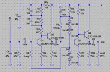
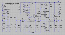
I went ahead with my project and actually built the thing. Instead of using separate diode strings for the bias, only one five-diode string was installed for both gain stages and both channels too. I also did other modifications to the component values and simulated with LT-Spice. The simplified diagram shows one channel, the final version includes power decoupling capacitors and a switch for input loading resistance and capacitance.
As soon as everything was soldered together, measured and tested on the workbench, I was ready for the real test. But then the old Sony turntable gave up breath, and didn't want to rotate anymore......
I never managed to repair the mysterious motor drive circuit, so the whole project has been shelved for more than two years now. Then, out of the attic came an old gramophone, dirty and rusty but it at least it was playing ok.
So now we are back in business, the preamp is going through testing, and it seems to be working as expected. Some of the components values have been modified, and more may be changed as we go, I will post an update later.
Anyway, it's nice to listen to some vinyl again...
Thank you all for the good advice and patience too.
I went ahead with my project and actually built the thing. Instead of using separate diode strings for the bias, only one five-diode string was installed for both gain stages and both channels too. I also did other modifications to the component values and simulated with LT-Spice. The simplified diagram shows one channel, the final version includes power decoupling capacitors and a switch for input loading resistance and capacitance.
As soon as everything was soldered together, measured and tested on the workbench, I was ready for the real test. But then the old Sony turntable gave up breath, and didn't want to rotate anymore......
I never managed to repair the mysterious motor drive circuit, so the whole project has been shelved for more than two years now. Then, out of the attic came an old gramophone, dirty and rusty but it at least it was playing ok.
So now we are back in business, the preamp is going through testing, and it seems to be working as expected. Some of the components values have been modified, and more may be changed as we go, I will post an update later.
Anyway, it's nice to listen to some vinyl again...
Attachments
Alternative Solution
It has been noted before, that this design (I'll call it Yang's from the original schematic) has a number of issues, of which one is fundamental.
The main problem is that the output from the first stage is taken relative to gound, when it should be taken relative to the supply line.
I have simulated it together with (principal) solution, please see the attached files:
"schematic compare.pdf", "PSRR compare.pdf", "output compare.pdf", "Yangs noise.pdf", and "NPN PNP noise.pdf"
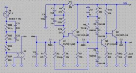
The lower part of the schematic is the original from Yang. The top part is my solution. Mind you, it is *a* solution - not *the* solution. Anyway, the Q1 stage is a simple flat 5.6x amplifier. The next stage takes the output from the first stage *relative to the supply line*. This is important. The output from Q2 is loaded with R6 and C5 which forms the 75usec part of the RIAA.
Now we are back to have the signal relative to ground. Another NPN-PNP stage including the 3180usec follows and the ouput is taken across R13 (It ought to have a buffer).
The file PSRR "compare.pdf": Instead of sending a signal through the input, the signal is input via the supply line. This should be an eye opener, the green graph is the output from the Yang design, and basically any noise on the power supply line is amplified 16 times! Ie. 1mV becomes 16mV on the output. That is definitely audible. The blue graph is the output from my design. While not being fantastic if you are used to OP-amp designs, it betters the the Yang design with 40dB or more, at 1.5kHz with 54dB!. So 1mV on the supply line becomes 10uV or less on the output!
The output graph only shows that the Yang design isn't perfect.
Noise: the main teaching is that the emitter resistor (R23) in the Yang design is the main source of noise (the blue-green graph): it's too large compared to the cartridge (the blue graph). It also shows, that it would probably be a good idea to include a subsonic filter to remove the noise below app 15Hz. Eg. a 3rd order 0.5dB Chebychev High Pass has a nice steep roll of.
Have a nice Day
Lars
It has been noted before, that this design (I'll call it Yang's from the original schematic) has a number of issues, of which one is fundamental.
The main problem is that the output from the first stage is taken relative to gound, when it should be taken relative to the supply line.
I have simulated it together with (principal) solution, please see the attached files:
"schematic compare.pdf", "PSRR compare.pdf", "output compare.pdf", "Yangs noise.pdf", and "NPN PNP noise.pdf"
The lower part of the schematic is the original from Yang. The top part is my solution. Mind you, it is *a* solution - not *the* solution. Anyway, the Q1 stage is a simple flat 5.6x amplifier. The next stage takes the output from the first stage *relative to the supply line*. This is important. The output from Q2 is loaded with R6 and C5 which forms the 75usec part of the RIAA.
Now we are back to have the signal relative to ground. Another NPN-PNP stage including the 3180usec follows and the ouput is taken across R13 (It ought to have a buffer).
The file PSRR "compare.pdf": Instead of sending a signal through the input, the signal is input via the supply line. This should be an eye opener, the green graph is the output from the Yang design, and basically any noise on the power supply line is amplified 16 times! Ie. 1mV becomes 16mV on the output. That is definitely audible. The blue graph is the output from my design. While not being fantastic if you are used to OP-amp designs, it betters the the Yang design with 40dB or more, at 1.5kHz with 54dB!. So 1mV on the supply line becomes 10uV or less on the output!
The output graph only shows that the Yang design isn't perfect.
Noise: the main teaching is that the emitter resistor (R23) in the Yang design is the main source of noise (the blue-green graph): it's too large compared to the cartridge (the blue graph). It also shows, that it would probably be a good idea to include a subsonic filter to remove the noise below app 15Hz. Eg. a 3rd order 0.5dB Chebychev High Pass has a nice steep roll of.
Have a nice Day
Lars
Attachments
Hi.
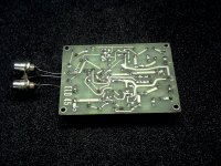
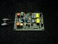
This one was published in the german electronic magazin ELO 9/1976, with PCB "ELO 45". I had one built at that time, but not used very long. Recently rediscovered in the crafting box.Here is another one I was looking into it recently after a member here made a request to check it out. Was sounding very nice to him but something was amiss. "Olson Mini Phono" he said. I have no other clue. ....
It's alive, it's not perfect, but it gets the job done!
@ LLPe, Thank you for the interesting article and the alternative diagram to the "Yang-Riaa" preamp. Slightly different and a little more complicated. I believe that I need to read it one more time and maybe run the spice side by side with my own setup.
@catd, Have you tested your preamp? If yes, how does it sound?
My version has already been in service for a couple of months now, and it seems to work as expected. Power it is fed by a regulator so hum from the power supply is almost non-existent. Noise, however, seems to be the biggest issue. When I turn the volume to max the white noise is very distinct, especially in the lower frequencies. But that was already predicted by the spice simulations, and we may agree on that the emitter resistor in stage one is the source. Furthermore there is a strange pumping sound in one of the channels, maybe it is caused by a faulty transistor..?
So it is not perfect and quite noisy but wait until the needle hits the groove, then the preamp noise is totally gone and drowned in noise from the record.
And is sounds good, nice and musical, and better than expected. At the end it is always quality of the recorded material which decides what comes out through the speakers. The described noise issue is not a problem for the daily use of the preamp.
So I will keep it as it is for a while, but maybe I need to find and replace the faulty device. I assume that there will be a version 2 one day, but that is a different story.
So for the curious ones: Go ahead and build one of your own...
@ NNX
I haven't tested it, I'm currently working on a design based on the same principle, but rather different at the same time. More on that in a different (future) thread.
On the strange pumping sound: I don't think it's a transistor, more likely either a faulty capacitor or some leak current. The latter can cause the DC operating point to change with a low frq. The phenomenon even has a name : motor boating. It can be seen in servo systems.
Hi.
This one was published in the german electronic magazin ELO 9/1976, with PCB "ELO 45". I had one built at that time, but not used very long. Recently rediscovered in the crafting box.
Info completed
You may even make it work again and then try the corrections I calculated for it. It would be a nice weekend project trip down the memory lane.Hi.
I built it some time after it was released and used it for several months. Cannot remember, if there where issues with sound. Later then I built Elektors Consonant + Pre-Consonant and ommited the ELO. Probably because I liked the Pre-Consonant better back then.
When the ELO-45 pcb fell into my hands again last year (after about 40 years), I replaced some electrolyts and added missing parts and tested it by hearing. It actually works inconspicuously, but sometimes seems something does not sound right.
Maybee I should test the improvements suggested by Salas in post #19.
Edit:
@Salas: you where a bit faster in writing.
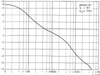
added: frequency response, how it was shown in the ELO-article.
Not to confuse: my comment was about the ELO-45 phono-pre ('Olson Mini') as shown in post #19....@catd, Have you tested your preamp? If yes, how does it sound?...
I built it some time after it was released and used it for several months. Cannot remember, if there where issues with sound. Later then I built Elektors Consonant + Pre-Consonant and ommited the ELO. Probably because I liked the Pre-Consonant better back then.
When the ELO-45 pcb fell into my hands again last year (after about 40 years
), I replaced some electrolyts and added missing parts and tested it by hearing. It actually works inconspicuously, but sometimes seems something does not sound right.Maybee I should test the improvements suggested by Salas in post #19.
Edit:
@Salas: you where a bit faster in writing.
added: frequency response, how it was shown in the ELO-article.
Attachments
Last edited:
If you will change the transistor types too it will be a more secure experiment since I had no spice models for the originals in post#19 and I modeled with equivalents. With these pin compatible low noise types here it will go same flat and it will gain 3dB more output also. It has below average sensitivity for MM cartridges so its good to add some.
edit: wrong schematic
edit: wrong schematic
Attachments
good morning...
I have already put in BC550 + BC560 because I had these and there were no transistors on the circuit board when I found it again. Probably used for other things over the years.
When I compared the CDIL BC414 / 415 and BC550 / 560 datasheets, I found them pretty similar.
When I have time and the right values C & R, I will try your suggestions in one channel to switch between the previous and the new version and listen if one can hear a difference.
If it turns out that the thing has any value, then a new PCB layout is probably appropriate because the original does not seem very useful.
Attachments
Last edited:
@Salas
You have accidentaly swapped collector and emitter for the BC327.
Lars
Good catch. Thanks. I restored the same mistake and replaced the sims both for original and new tweaked values in post#19
good morning...
I have already put in BC550 + BC560 because I had these and there were no transistors on the circuit board when I found it again. Probably used for other things over the years.
When I compared the CDIL BC414 / 415 and BC550 / 560 datasheets, I found them pretty similar.
When I have time and the right values C & R, I will try your suggestions in one channel to switch between the previous and the new version and listen if one can hear a difference.
If it turns out that the thing has any value, then a new PCB layout is probably appropriate because the original does not seem very useful.
They should be very similar. Please look back in post #19 for the changed values suggestions after Q2's orientation mistake was restored. Pay attention to the lower C1 value too. Can be a small Wima MKP now.
That Q2 orientation mistake made #28 wrong and invalid as well. There's no gain or noise difference if changing to the 337/327 types anymore.
Hello...
@Salas: thank you for your efforts.
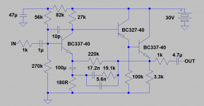
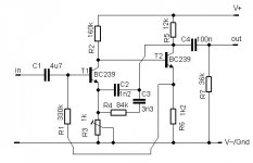
If anyone is interested in an even simpler circuit: these I just have found in my notes.
If I remember correctly:
I bought it some decades ago as ready to use device, it came in an enclosure along with a built in small power supply.
I have only leftover this circuit drawing, and don't know the exact supply voltage, must be around 24Volts.
It sounded a bit bass accentuated, but perhaps only in the context of the then used Ortofon F15.
@Salas: thank you for your efforts.
If anyone is interested in an even simpler circuit: these I just have found in my notes.
If I remember correctly:
I bought it some decades ago as ready to use device, it came in an enclosure along with a built in small power supply.
I have only leftover this circuit drawing, and don't know the exact supply voltage, must be around 24Volts.
It sounded a bit bass accentuated, but perhaps only in the context of the then used Ortofon F15.
Attachments
Hello
The way T2's collector DC voltage centers between +Rail and GND when simulating with BC550C substitutes in Spice, better use a 18V PSU.
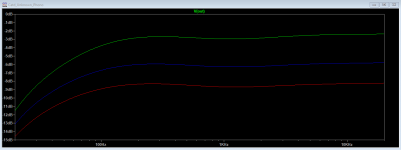
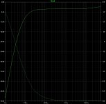
The R3 rheostat's setting affects gain and frequency response. 0dB is 1V in the attached chart for three different good R3 settings. 500Ω 750Ω 1kΩ top to bottom. Input is 5mV. Most normal for MM gain and better hiss is the 1kΩ red curve setting. At 100Ω (not shown) the circuit produces much total output with a very shallow under 1kHz curve and much tilted up treble. Obviously loses control with a too low R3 value. 350Ω should be R3's border balanced setting.
So when looking at proper setting area frequency response curves, they simulate as upper bass & low mid range little accentuated indeed. Although there is not much low bass in this phono, to the human ear the upper bass area is where a fuller lows feeling comes from. If in combination with some high octave recess also, that fullness hump becomes more present. A little like when listening with headphones as Sennheizer HD 650 I would dare say. Can't sustain real lows level due to a small diaphragm in an open frame but tricks us with an under 1kHz progressive hump to satisfy for lower tones feel in music. While its a little veiled in the treble also. But if it has to be a compromise, rounder is safer than brighter to most people. You seem to remember that phono circuit's sound well.
The way T2's collector DC voltage centers between +Rail and GND when simulating with BC550C substitutes in Spice, better use a 18V PSU.
The R3 rheostat's setting affects gain and frequency response. 0dB is 1V in the attached chart for three different good R3 settings. 500Ω 750Ω 1kΩ top to bottom. Input is 5mV. Most normal for MM gain and better hiss is the 1kΩ red curve setting. At 100Ω (not shown) the circuit produces much total output with a very shallow under 1kHz curve and much tilted up treble. Obviously loses control with a too low R3 value. 350Ω should be R3's border balanced setting.
So when looking at proper setting area frequency response curves, they simulate as upper bass & low mid range little accentuated indeed. Although there is not much low bass in this phono, to the human ear the upper bass area is where a fuller lows feeling comes from. If in combination with some high octave recess also, that fullness hump becomes more present. A little like when listening with headphones as Sennheizer HD 650 I would dare say. Can't sustain real lows level due to a small diaphragm in an open frame but tricks us with an under 1kHz progressive hump to satisfy for lower tones feel in music. While its a little veiled in the treble also. But if it has to be a compromise, rounder is safer than brighter to most people. You seem to remember that phono circuit's sound well.
Attachments
Installed and in use.
Hello again, the experimental "Yang-Riaa" preamp is now installed in my diy amp and lid closed. As mentioned before, it's perfect, quite noisy and has some strange "pumping" sound in the right channel. I tried to localize the source but failed, so we will have to live with that for a while. But hum is not a problem, since there is a regulator, large decoupling capacitors, proper star grounding and "balanced" wiring all the way to the pick-up.
This is my first riaa preamp and and it makes it possible to listen to vinyl again, oh yeah! And it is definitely not the weakest link in the signal chain, I believe that may be the recording or vinyl itself. In other words, a good recording sounds wonderful and a bad one horrible.....
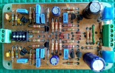
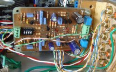
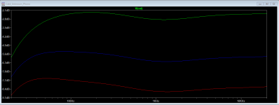
So thank you all for your input good advice during this design and build! Attached is modified schematics, installation photo and RIAA response and noise plots. Comments are welcome!
@catd: That's a cute old device, please tell about your resuls. Maybe an Olson Mini will be my next project...?
@LLPe: I am not sure if it's motorboating, since that usually comes as a very distinct and "pumping" sound at a more constant frequency. This is very weak, similar to the other noise level, and with more random frequency. That's why I suspect it may be a faulty device, they sometimes behave like that. Anyway, your version looks interesting too, please post results...
Hello again, the experimental "Yang-Riaa" preamp is now installed in my diy amp and lid closed. As mentioned before, it's perfect, quite noisy and has some strange "pumping" sound in the right channel. I tried to localize the source but failed, so we will have to live with that for a while. But hum is not a problem, since there is a regulator, large decoupling capacitors, proper star grounding and "balanced" wiring all the way to the pick-up.
This is my first riaa preamp and and it makes it possible to listen to vinyl again, oh yeah! And it is definitely not the weakest link in the signal chain, I believe that may be the recording or vinyl itself. In other words, a good recording sounds wonderful and a bad one horrible.....
So thank you all for your input good advice during this design and build! Attached is modified schematics, installation photo and RIAA response and noise plots. Comments are welcome!
@catd: That's a cute old device, please tell about your resuls. Maybe an Olson Mini will be my next project...?
@LLPe: I am not sure if it's motorboating, since that usually comes as a very distinct and "pumping" sound at a more constant frequency. This is very weak, similar to the other noise level, and with more random frequency. That's why I suspect it may be a faulty device, they sometimes behave like that. Anyway, your version looks interesting too, please post results...
Attachments
C4/R7 at the output form a 44 Hz high pass. If one increase or omit R7, the curve would decrease less in the lower range, I think.... Although there is not much low bass in this phono...
Probably this should be a very simple subsonic filter.
As I have seen in simulation analysis without that specific R7 value the upper bass booms. That's why the designer probably put it there so to fix that filter for any higher following line preamp's impedance. See here with R7 100kΩ
Attachments
@nnx
Change your R36 to 560Ω and your R37 to 40Ω and run Spice again so to see if you got more HF in reality than in the original simulation thus more hiss. Pick signal from top of R36 for MM like attenuation, top of R37 for MC like attenuation. Also, yes same type transistor samples can have more noise than other samples. Or weird noises that the others lack. If you can manage a higher value C1 with still good overall frequency response by manipulating your phono's RIAA values you will probably deflate that noise bump at VLF to a useful degree
Change your R36 to 560Ω and your R37 to 40Ω and run Spice again so to see if you got more HF in reality than in the original simulation thus more hiss. Pick signal from top of R36 for MM like attenuation, top of R37 for MC like attenuation. Also, yes same type transistor samples can have more noise than other samples. Or weird noises that the others lack. If you can manage a higher value C1 with still good overall frequency response by manipulating your phono's RIAA values you will probably deflate that noise bump at VLF to a useful degree
I used a 2N5210 as a first stage flat gain into an op amp RIAA in 1986. so far the best I've heard I am upgrading the sx780 preamp to this but only have 2SC1815Y which appear to have slightly more noise.
you could change R6 to 4.7k and R3 to 1.5m for more gain
you could change R6 to 4.7k and R3 to 1.5m for more gain
Last edited:
@ Salas:
Thank you for your advice!
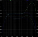
I have made the modification to the Riaa generator as you described, and it'a quite surprising to see the frequency response in the HF area. The green curve shows +20db around 1 Mhz and that is quite a lot. I wonder if adding a zobel network as suggested will make any difference (blue curve)?
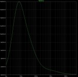
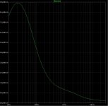
I also made a noise simulation with a different input capacitor, C1=500nF. It shows less noise, but only at the very low frequencies around 20Hz, and has almost no effect above 50Hz. The Riaa curve doesn't change much, only minor adjustments may be needed.
The strange noise described above seems to be a transistor related phenomenon called "popcorn noise", and the cure is finding and replacing the transistor.
@ Stocktrader200:
Changing the first transistor may be an option, I have 2N5209, 2SC945 and BC550 in my collection. Reducing R6 to 4k7 will double the gain and reduce the noise a little. It will also alter the riaa equalization, so some adjustment will be needed there too.
On the other hand, if we reduce R4~R6 and R24 with a factor 100, and increase C2 and C2 100 times, then the noise will be reduced around 4 times. Maybe that is the way to go?
Anyway, the preamp is now inside the main amp case, so any modifications will be made next time it is opened for service and modifications. In the meantime, maybe it would be fun to start on another Riaa preamp project.....?
Thank you for your advice!
I have made the modification to the Riaa generator as you described, and it'a quite surprising to see the frequency response in the HF area. The green curve shows +20db around 1 Mhz and that is quite a lot. I wonder if adding a zobel network as suggested will make any difference (blue curve)?
I also made a noise simulation with a different input capacitor, C1=500nF. It shows less noise, but only at the very low frequencies around 20Hz, and has almost no effect above 50Hz. The Riaa curve doesn't change much, only minor adjustments may be needed.
The strange noise described above seems to be a transistor related phenomenon called "popcorn noise", and the cure is finding and replacing the transistor.
@ Stocktrader200:
Changing the first transistor may be an option, I have 2N5209, 2SC945 and BC550 in my collection. Reducing R6 to 4k7 will double the gain and reduce the noise a little. It will also alter the riaa equalization, so some adjustment will be needed there too.
On the other hand, if we reduce R4~R6 and R24 with a factor 100, and increase C2 and C2 100 times, then the noise will be reduced around 4 times. Maybe that is the way to go?
Anyway, the preamp is now inside the main amp case, so any modifications will be made next time it is opened for service and modifications. In the meantime, maybe it would be fun to start on another Riaa preamp project.....?
Attachments
- Home
- Source & Line
- Analogue Source
- Discrete phono stage, single supply.