Hi all,
after posting a thread years ago and becoming exceedingly confused about cartridge step up maths, I gave up, embarrassing for a math major..perhaps I should have studied electrical engineering. Recently I have been reading up on this topic and would like to once and for all figure out how to run the math/electronic theory to find the correct step up to mate with a MC cartridge.
I have looked at 2 different links.
Link (1)
SUT
and
Link (2)
mc step-up transformers explained
Now, everything I read in link 2 falls apart after reading what is on link 1 and I am once again confused about what to look for in a MC step up.
In the second link the author explains that you simply apply a 2 step process: A. multiply the turns ratio by the cartridge output to find the voltage and make sure that it is not overloading the MM phono stage input (i.e/ between 2.5 and 10 MV) and then B. Perform the calculation to show you how much resistance the cartridge actually sees and apply a rule of thumb at least 3 to 10 times ratio between the source impedance and the input. The rule is for the most part out of thin air, though he does explain that matching to equate them in terms of impedence is a bad idea.
In the first link however, the author takes a different approach. He explains that a turns ratio cannot just be multiplied to give you the voltage on the other end. For example the cinemag 3440 cart used with the denon 103 illustrates the point. The output is .30 MV and the turns ratio is 35.4 resulting in 10.6 MV out. Now here is the bit I need help with. He explains that in reality the with this combination the output is really 5.1387mV NOT 10.6MV. He uses this equation to adjust the 10.6 MV to 5.1387MV:
Equation (*)
(Vout / Vcart) = (R(Load_effective) / (R(Load_effective) + (Rcart)))
he finds Vout and then Multiplies by the turns ratio.
The parameters are as follows:
Turns ratio: The turns ratio of the step up device
Rcart: is internal resistance of the MC cartridge
R(Load_effective): resistive load seen at the MC cartridge defined as 47,000/(Turns Ratio)^2
Vout: Voltage output at secondary side of tranny
Vcart: Voltage output at MC cartridge
for this example they using a denon 103 + cinemag 3440 are:
Turns Ratio: 35.4
Rcart: 40
R(Load_effective): 47,000/(35.4^2) = 37.5 ohms
Vout: to be solved for
Vcart: .30 MV
Putting it into equation (*) and solving yields
.1452mV for Vout.
He then takes Vout and multiplies by the turns ratio.
.1452 * 35.4 = 5.1387mV
NOW: If you take the simple method (from link 2 by multiplying turns with output) you get 10.6 MV, using this adjusted method with equation (*) you get 5.1387 MV. So my question is this. What is equation (*), is there some theory here that I am missing, is this voodoo? I would like a reliable way to select components that match, though I have trouble trusting the equation (*) method without knowing why he is using it and what it is. I certainly want to get this ironed out before I start buying different transformers to play with, and any help with this would be greatly appreciated. Thanks.
Mmmm, my belief is that using a SUT and attempting to get the correct LOMC cart loading ... is like p*ss*ng into the wind! 
If you want to get serious about LOMC cart loading and you have a MM phono stage, use an (active) head amp. If it's built right, this will have a parallel pair of input RCAs:
* one pair is for the phono stage.
* the second is for "R-loaded" plugs.
Regards,
Andy
If you want to get serious about LOMC cart loading and you have a MM phono stage, use an (active) head amp. If it's built right, this will have a parallel pair of input RCAs:
* one pair is for the phono stage.
* the second is for "R-loaded" plugs.
Regards,
Andy
Archiekaras your link 2 is the more useful for showing the effects that impedance loading has on the transformer.The only aspect missing concerns how the combined source impedance of the cartridge with the xformer effects the noise figures of the preamplifier.As a rule of thumb,as there are a myriad of variations in topologies, valve stages give lower noise with about four times the source impedance of transistor ccts which typically have their lowest noise with a source impedance of 5000 Ohm.
Hi,
The maths in both links is right but the theory in SUT is wrong.
The Denon DL103 simply needs a 1:10 step up like :
Denon Step Up transformer,Denon AU-300LC Step Up transformer,Denon AU 300LC Step Up transformer,Denon AU300LC Step Up transformer,Denon AU-300LC MC Step Up transformer,Denon AU 300LC MC Step Up transformer,Denon AU300LC MC Step Up transformer
Its not more complicated. The 40ohm cartridge sees 470 ohms,
load, and conversely the 47K input sees a 4K ohm drive source.
Gain is x10, 0.3mV goes to 3mV, moreorless which is just fine.
The SUT post shows your really wasting your time using
any transformer that breaks the > 3 times loading rule,
The above is the ~ x10 case.
So with a 1:33 transforrner the cartridge sees 47 ohms
as a load and the input sees a 40K ohms driving source.
So you will get high voltages losses both ends and about
the same real output as the first case, nowhere near 10mV.
In reality 1:20 would work, the cartridge sees around
120 ohms and the input is driven by about 16K ohms.
This will give you the "highest" voltage gain, about 5mV.
This is the ~ x3 case.
However its easier to build lower ratio high quality transformers.
Here the DL103 is fine with a ratio of 1: 10 to 20, and most
MC's are fine using a transformer that fits into x3 to x10 case.
rgds, sreten.
archiekaras-
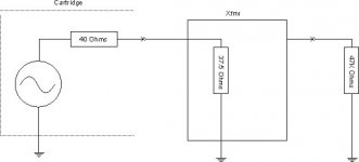
sreten has the most practical answer. If you are still wondering where the math is coming from, it has to do with how they rate the output of the cartridge. If .3mV is the open circuit voltage output of the coil, then the 2nd link is the most accurate. Transformers don't really have an impedance unto themselves, they transform the impedance from one side as seen by the other side by a factor of the turns ratio squared. So a 34.5 turns ratio xfmr will transform the 40K Ohm load impedance to 37.5 Ohms on the other (cartridge) side of the xfmr. The cartridge then sees a load of 37.5 Ohms which forms a simple resistive divider as shown in the attached image. The voltage developed across the cartridge side of the xfmr is then .3mV x 37.5/77.5 or .1452mV. The xfmr steps this voltage up by a factor of the turns ratio (x 35.4) so it delivers 5.186mV across 40K.
If the cartridge output is rated .3mV into a 40 Ohm load, then the 1st link is most accurate. In that case, the resistive divider is already factored in and the cartridge will deliver .3mV across 40 Ohms since it would have .6mV output open circuit (the 40 Ohm load and the 40 Ohm source imp form a voltage divider that will halve the open circuit voltage or 40/80). If the xfmr presents a 37.5 Ohm load instead of 40 Ohms, the voltage would then be .29mV since the voltage divider would be 37.5/77.5 x .6mV. The xfmr steps this up by 35.4x or 10.28mV.
Attachments
Hi,
The error in post #1 and #5 and point 1) is only considering
one side of the transformer matching for alleged gain.
Work out what happens with :
40-47, 33 gain and 40K-47K.
Compare to :
40-120, 20 gain and 16K-47K
And :
40-470, 10 gain and 400-47K.
rgds, sreten.
The error in post #1 and #5 and point 1) is only considering
one side of the transformer matching for alleged gain.
Work out what happens with :
40-47, 33 gain and 40K-47K.
Compare to :
40-120, 20 gain and 16K-47K
And :
40-470, 10 gain and 400-47K.
rgds, sreten.
Last edited:
I do not understand what was said. The open circuit/drive into terminology has confused me. When I look at a cartridge, specification it is called output voltage measured at 5cm/sec. The impedance is called internal impedance. So I am not sure which of the 2 scenarios you are talking about is in play with a MC cartridge. So it leaves me confused how to apply voltage divider theory, also does it apply the same way when a passive transformer is in the circuit as it does with the typical resistor in circuit examples they give online for voltage dividing.
If I were to guess I would think that it is putting out 0.3 MV from the output pins after being run though a 40 ohm (internal impedance) load.
Is the voltage drop/adjustment equation correct ? Under what scenario will it correctly give you the real voltage seen by the MM phono section.
If I were to guess I would think that it is putting out 0.3 MV from the output pins after being run though a 40 ohm (internal impedance) load.
Is the voltage drop/adjustment equation correct ? Under what scenario will it correctly give you the real voltage seen by the MM phono section.
dfoe-
It all depends upon how the output is specified (I actually don't know which method they use). Think of the cartridge as an AC generator with an internal impedance. If it has and internal impedance of 40 Ohms and you measure the output with no load, it will appear ~twice as high as if it were terminated into a 40 Ohm load. So the question becomes: Is the 0.3mV output measured open circuit or into a 40 Ohm load?
Regarding the xfmr, per my previous post, xfmrs do not exhibit an impedance of their own when operated within their specified range. The 40 Ohm load presented by the xfmr to the cartridge is the result of the 40K termination on the other side being transformed by the square of the turns ratio. The xfmr does not have a 40 Ohm input impedance unless it is terminated on its output by 40K. You do not have to apply the voltage divider reduction again on the output side of the xfmr. If you run the xfmr with no output load, the input side will be essentially open circuit as well and the voltage seen by the input will double (and so will the output voltage). Terminating the output with 40K will restore the voltage ratio as it now properly terminates the cartridge with 40 Ohms. Not sure what sreten is alluding to...
The question still remains then: How is the cartridge output voltage specified; open circuit or terminated into the specified impedance?
not to be rude but why use a step up transformer when you could build a nice MC phono stage that can be configured to any MC cartridge loading with the change of a few resistors. then all you do is plug the phono stage into any line level input of your pre/integrated amp.
or am i missing an important point of step up transformers.
or am i missing an important point of step up transformers.
or am i missing an important point of step up transformers.
Noise and CMR.
Noise and CMR.
Care to elaborate on that? Currently using an SUT for my MC-cart in combination with a MM-pre. Pretty happy about it, but not afraid of trying to make a separate MC-head
... but not afraid of trying to make a separate MC-head
Why don't you do it, then!
Threads like this are just a polarised slag-fest ... "SUTters" putting forward all sorts of justifications why a transformer is the only way to go ("noise and CMR" ) while adherents of a JFET-based head amp do the same.So you really have to build one, to find out for yourself.
All I will say is:
1. the SLA-powered, JFET based head amp that I use is dead quiet. You cannot hear it above the intrinsic noise of a phono stage.
2. cart loading is easy; the head amp has a default 47K load res ... and a parallel pair of input RCAs, so you can plug in "loaded" RCA plugs into the 2nd pair.
Regards,
Andy
a transformer is the only way to go ("noise and CMR"
I didn't use the word "only."
But there are a lot of advantages to it, if done correctly. It's rarely done correctly.Nice article SY, enjoyed reading that. I'm no tube junkie though, but gave me some good insights.
Andyr, I do not think a FET-preamp is suited for cartridges/transformers that are loading your stage with a low impedance. Bipolar inputs should give you better noise performance. If you're running an MM with say, stock 47K input impedance (or higher (100k) for Quadrophonic carts), in that case, choose FET; you'll have better performance due to lower current noise (which is the dominant factor for noise there). With an MC and lower input impedance; you're looking at voltage noise as primary contributor, which is lower in bipolar inputs.
The ADA4898-2 seems like the ideal candidate for a MC-headamp.
Andyr, I do not think a FET-preamp is suited for cartridges/transformers that are loading your stage with a low impedance.
Mmmm, Wirehead, you're not making much sense, IMO.
I'm talking about a "head amp" which boosts the signal from a LOMC cart so it can be fed into a MM phono stage. A transformer doesn't fit into the picture.I do not think a FET-preamp is suited for cartridges/transformers that are loading your stage with a low impedance.
When a LOMC plugs into a head amp, the cart loading takes place at the input of the head amp. The output impedance of the head amp will generally be very low - so it will easily "feed" the 47K Zin of a typical MM phono stage.
IOW, the head amp "loads" the phono stage.
Andyr, I do not think a FET-preamp is suited for cartridges/transformers that are loading your stage with a low impedance. Bipolar inputs should give you better noise performance. If you're running an MM with say, stock 47K input impedance (or higher (100k) for Quadrophonic carts), in that case, choose FET; you'll have better performance due to lower current noise (which is the dominant factor for noise there). With an MC and lower input impedance; you're looking at voltage noise as primary contributor, which is lower in bipolar inputs.
That's your opinion, Wirehead ... I'll ask the designer of my head amp why he chose to use JFETs - I suspect he will say they are (despite their idiosyncrasies) ideal for small-signal components ... phono stages, microphone amps ... and head amps.
Regards,
Andy
Hi Andy, sorry if it's not that clear. Maybe this will explain it better. If using e.g. an op amp as head-amp; You'll be loading the MC-cart/Head-amp with a low impedance resistor (input side) - e.g. 100ohm. A bipolar input will get you better (lower) noise floor than a FET-input in this case.Mmmm, Wirehead, you're not making much sense, IMO.
Now for the case of the MM-phono stage that follows the head-amp; you can get away with a lower input impedance as well. The regular 47k input can be changed to a lower value. If that's the case, then bipolar inputs should have a lower noise floor (all depends on the implementation) compared to FET's.
That's what I was hinting on. If you can vary your input impedance, and you don't need high impedance, then you can reach lower a noisefloor with bipolar inputs. And with step-up transformers, or diy-head-amps, you can get away with that lower impedance quite easily.
That's your opinion, Wirehead ... I'll ask the designer of my head amp why he chose to use JFETs - I suspect he will say they are (despite their idiosyncrasies) ideal for small-signal components ... phono stages, microphone amps ... and head amps.
Regards,
Andy
Fully agree, all comes down to preference and taste. But that should not be an excuse to question things
Edit: maybe we should make a separate topic about this
Hi,
Whilst I agree that there are advantages I also know that there are limitations. There always are.
From my admittedly limited experience with SUTs it takes a truly exceptional design to beat a well designed active circuit.
It's not as if xformers are noiseless either.
Granted, most commercially available active designs are far from perfect.
For some weird reason this area has been greatly neglected but I'm pretty sure it can be done.
Balanced or not balanced, hollow state or discrete. Stand alone stage or integrated.
It's not even so hard to do with a trioded penthode a la DA3, a EC8010 or even a more common 6DJ8 (when //ed).
And if you use a SUT, why not run it in balanced mode? After all a MC is a balanced source.
Ciao,
I didn't use the word "only."
Whilst I agree that there are advantages I also know that there are limitations. There always are.
From my admittedly limited experience with SUTs it takes a truly exceptional design to beat a well designed active circuit.
It's not as if xformers are noiseless either.
Granted, most commercially available active designs are far from perfect.
For some weird reason this area has been greatly neglected but I'm pretty sure it can be done.
Balanced or not balanced, hollow state or discrete. Stand alone stage or integrated.
It's not even so hard to do with a trioded penthode a la DA3, a EC8010 or even a more common 6DJ8 (when //ed).
And if you use a SUT, why not run it in balanced mode? After all a MC is a balanced source.
Ciao,
- Status
- This old topic is closed. If you want to reopen this topic, contact a moderator using the "Report Post" button.
- Home
- Source & Line
- Analogue Source
- Moving Coil Step Up Maths and Optimal Matching