It would help if you described your test setup a little better, along with the circuit you tested. I might try a scan with a modulated current source to look at output impedance vs. frequency. I'd like to keep the low ESR caps at the regulator output, but no one says they have to have a huge capacitance associated with them (good high current polypropylenes or stacked-film polyesters come to mind). Easy to simulate, anyway.
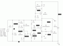
The circuit is the one you proposed in post 17. It appeared to me that value of C4 significantly over-damped the response, so I used a sine wave to look at the non-linearity - in simulation, of course. The idea wasn't original to me, but suggested by one of the folks corresponding to the regulator shoot-out article in Linear Audio.
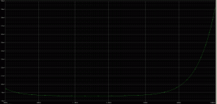
Here's an output impedance scan taken by placing both a 0.1 A static load and a 0.02 A sine wave load on the output of the series-pass regulator. It looks like next time around I could use just the sine-wave current source, as it has provision for DC bias. I kept the 1300uF output capacitor with 5 milliohm impedance.
The schematic is attached for reference. I used a 1uF coupling capacitor with 100k (1M) to probe the output voltage excursion.
The schematic is attached for reference. I used a 1uF coupling capacitor with 100k (1M) to probe the output voltage excursion.
Attachments
Here's the output scan - divide the results by 0.02 to get the effective output impedance. The loop is still working to reduce the output impedance at 100 kHz, as you still don't get the full 0.02A X 0.005 ESR X Current signal at 100kHz. Next up would be to try this with some nice simulated film caps (Lower ESR) to look at both this plot and the time-domain transient response. I have a bunch of 2 uF Evox polypropylene caps that may be just the ticket.
Attachments
I've tried several frequency scans using equivalents of 4 X 47 uF 50V polymer coas (22 milliohms ESR) and 4 X 2uF film caps ~15 milliohms as measured by an impedance analyzer). They all loko about the same as the plot shown here, wth the polymer caps being marginally better (at 2 bucks per bitty cap, they'd better be). Next I have to look at transient response, and maybe try looking at harmonic products..
I brought in one of my Evox 2.2 uF PMR series caps to measure it on the HP4194A impedance/G-P analyzer today at work. These are metallized polypropylene capacitors designed for high frequency, high current duty in demanding apps like switching power supplies. The effective resistance clocked in at ~7.5milliohms, lower than the calibration short for the instrument (which probably needs to be cleaned and polished). I'm going to be conservative and say the cap has an ESR of ~ 5 mohm for purposes of simulation. More later...
Yee-haw...
The frequency domain plots don't tell everything. With 4 of the Evox film cpas in place, the time domain simulation shows oscillation. With a cap of 190uF, 5 milliohms (representing 4 X Nichicon 47 uF, 50V polymer caps), the response is crisp and well-damped. Incidentally, this combination with the ploymer caps is also the combination that fared the best in the output impedance scan, though only by a whisker.
The frequency domain plots don't tell everything. With 4 of the Evox film cpas in place, the time domain simulation shows oscillation. With a cap of 190uF, 5 milliohms (representing 4 X Nichicon 47 uF, 50V polymer caps), the response is crisp and well-damped. Incidentally, this combination with the ploymer caps is also the combination that fared the best in the output impedance scan, though only by a whisker.
I found a sine current source in my PSpice suite that will be suitalble for doing Fourier plots of power supply response, so I'm going to do the time domain, frequency domain, and Fourier plots for the series pass regulator with simulated 4 X 47uF, 50V polymer caps at the output. I might possibly be able to stabilize the simulation with film cap loading, but I don't want to go to the trouble at this moment. I'll then switch to regulator #2, which is essentially an open loop boosted zener diode. I'm curious how it will look with various capacitive loads.
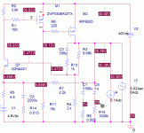
Here is the variant of the series pass regulator used for time domain pulse response, output impedance vs. frequency, and fourier /THD analysis. The output capacitace represents 4 pieces of a Nichicon 47uF, 50V polymer capacitor, 22 milliohms ESR, so the composite capacitor is 190 uF, 5 miliohms. A 1uF coupling cap in series with a 1M (1000k) resistor is used as an output probe.
Attachments
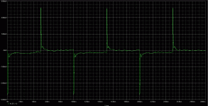
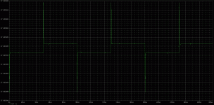
Here's the time domain pulse response to a fast 50 mA current pulse. The regulator responds cleanly to the current pulse, but there is also low level "squiggle" between whacks. Is this important? Maybe - we'll see later. You don't see the low level garbage with #2 regulator, the boosted zener.
Attachments
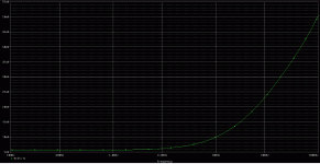
Hese's a an output impedance scan using a 20mA swept sinewave current source superimposed on a 0.1 A DC load. To get the output impedance, divide the voltage shown on the graph by 0.02. This scan looks benign, but it doesn't tell the whole story, as I have mentioned earlier.
Attachments
Last edited:
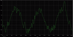
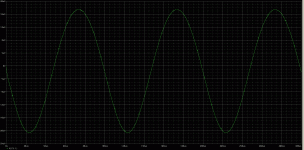
Here's the response to a 10 kHz, 20 ma sine current source superimposed on a 100 mA DC load. You would expect to see a relatively clean-looking sine response, so what's all the crud riding on the basic waveform? Keep in mind, this regulator hasn't been built yet. It looks like there's some fixing left to do, probably in the realm of improved compensation.
Attachments
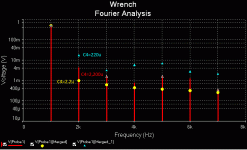
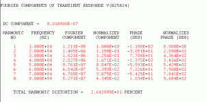
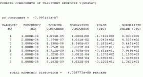
Here's what that crud does to the output THD, pretty much in line with what jackinnj observed a few posts ago. The more telling plot is the previous one showing the response to a clean sine wave excitation. I suspect that the crud shown in that picture is similar in nature to the stuff that shows up in the pulse response. At any rate, something still needs fixing. I'll post the results when I figure things out, but I won't promise when...
So - there are three ways to look at your simulated power supply. Each gives a piece of the picture, but not the whole story - best to do all three.
So - there are three ways to look at your simulated power supply. Each gives a piece of the picture, but not the whole story - best to do all three.
Attachments
OK, this is a repeat of the aforementioned zener diode-based shunt regulator scheme, with a 190 uF, 0.005 ohm output cap representing 4 X 47 uF, 50V Nichicon polymer capacitors. I may try a pulse response using film capacitors instead to see if this regulator fares better with small value, low ESR caps than the series regulator did.
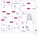
The schematic here shows the basic circuit used in the simulations. The output load will vary depending on simulation type - in the schematic, it's set up for pulse loading to get a time-domain response.
The schematic here shows the basic circuit used in the simulations. The output load will vary depending on simulation type - in the schematic, it's set up for pulse loading to get a time-domain response.
Attachments
Last edited:
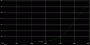
With the pulsed load replaced by a swept sine current source with 0.02A AC component and 0.1A DC bias, here's a plot of the output voltage excursion that can be used to calculate output impedance vs. frequency. Divide the voltage excursion by 0.02 to get output impedance. This regulator starts with higher output impedance than the series pass regulator, but is lower impedance at high frequency.
Attachments
Here's the THD of the response shown in the previous post. I'm not sure what this data really means, as the output excursion is so small to begin with. Perhaps I should check out the regulator shoot-out article in Linear Audio cited by Jackinnj. At any rate, the visible dirt shown in the linear regulator's response to sine wave excitation is absent here, and the THD is less.
Attachments
I ran a bunch of regression analyses on the regulator "scores", trying to tease out a relation between PSRR, noise and Zout -- the R^2s weren't great -- when a reader responded to Jan that the regulators may be causing harmonic products on the rails I investigated further and it seemed that the low-ish THD regulators consistently ranked higher in subjective analysis.
Mind you that i purposely used a very low noise, low THD line amplifier to be subjected to test -- the Borbely All JFET line amp -- it only has 40dB PSRR.
Mind you that i purposely used a very low noise, low THD line amplifier to be subjected to test -- the Borbely All JFET line amp -- it only has 40dB PSRR.
- Status
- This old topic is closed. If you want to reopen this topic, contact a moderator using the "Report Post" button.
- Home
- Source & Line
- Analogue Source
- Low Noise Discrete Power Supplies for Phono/Line Preamps
