I had a similar experience with the TD-124 which I found I liked a whole lot better than my 125.
There will probably be a micro, but not for a while - the 6F12P has been suggested and I have been curious about this type and will check it out.")
Some more investigation into noise performance tonight to see if there is more I an eek out of this thing.
There will probably be a micro, but not for a while - the 6F12P has been suggested and I have been curious about this type and will check it out.
Some more investigation into noise performance tonight to see if there is more I an eek out of this thing.
Mogens,
One 6f12p per channel is fine; there is a schematic somewhere on the internet if you don't feel like designing your own. There will be quite a lot of miller capacitance in the second (triode) stage-maybe 300-400pf so make sure and include this in your RIAA calculations. Going into a 10k input impedance after the phono wouldn't be too great either-100k should be much better.
I have not found the 6f12p to be as variable as the 6j52p discussed here-although it does share a similar "dog's hind leg" appearance.
Last edited:
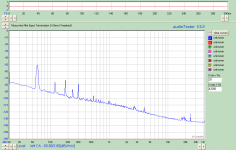
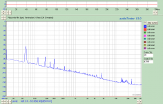
I did some noise measurements with the input shorted, shunted with 100 ohms, and open with just the 47K load resistance. It turns out that I am still having EMC problems with the generator output of the millet sound card interface due to conducted emc on the cables, but there may be more to it. I will investigate further, but I will try running the generator output at 1.0V out and doing the attenuation externally and see how that goes.
See the 0 ohm measurement for the 6ж9п-EB / 6Z9P-EV and the D3A, clearly the D3A is quieter, but by a small number of dB. The numbers are about 4.4dB better than shown
See the 0 ohm measurement for the 6ж9п-EB / 6Z9P-EV and the D3A, clearly the D3A is quieter, but by a small number of dB. The numbers are about 4.4dB better than shown
Attachments
I had a similar experience with the TD-124 which I found I liked a whole lot better than my 125.
There will probably be a micro, but not for a while - the 6F12P has been suggested and I have been curious about this type and will check it out.
Some more investigation into noise performance tonight to see if there is more I an eek out of this thing.
Hi Kevin,
I hope I didn't lead you into wasting money
. But, it is an insteresting valve with som impressive data. I'm curious to see what you find.Cheers,
Mogens
Hi Piano3,
Thanks, I will try google. Always good to get inspiration. I'm usually a solidstate guy, but I have always had a soft spot for valves.
I have admittedly only designed a few valve RIAA stages, the last one being 15 years ago. ECC83/ECC82, if memory doesn't fail me. However, the purpose at the time was not fancy valves, but to explore current source anode load and battery for grid supply. As I remember it played rather nicely. I think I still have it somewhere.
Btw. I also have a few 6S17K, which I know you have used. I also considered trying these out as input stage. To little time...
Cheers,
Mogens
Thanks, I will try google. Always good to get inspiration. I'm usually a solidstate guy, but I have always had a soft spot for valves
. I have admittedly only designed a few valve RIAA stages, the last one being 15 years ago. ECC83/ECC82, if memory doesn't fail me. However, the purpose at the time was not fancy valves, but to explore current source anode load and battery for grid supply. As I remember it played rather nicely. I think I still have it somewhere.
Btw. I also have a few 6S17K, which I know you have used. I also considered trying these out as input stage. To little time...
Cheers,
Mogens
Mogens,
One 6f12p per channel is fine; there is a schematic somewhere on the internet if you don't feel like designing your own. There will be quite a lot of miller capacitance in the second (triode) stage-maybe 300-400pf so make sure and include this in your RIAA calculations. Going into a 10k input impedance after the phono wouldn't be too great either-100k should be much better.
I have not found the 6f12p to be as variable as the 6j52p discussed here-although it does share a similar "dog's hind leg" appearance.
Hi MKC,
No you didn't waste my money. I was curious anyway and had planned on something with the 6F12P for some time. I tried to buy ones based on the provided pictures that appeared to be well made, I saw plenty of examples of crooked envelopes in addition to crooked insides. This seems to be a particularly Russian problem although I have seen a few American and European tubes with this issue as well. Oddly I can't recollect having ever seen a Chinese tube with this issue, although I have experienced plenty of other issues with them. I don't have any current production, but some of the dhts seem to be both nice sounding and reliable. (TJ in particular)
The next step of course will be to curve both the pentode and triode sections and do some work in spice. The triode has pretty high mu, but the high transconductance also implies a reasonably low rp compared to anything I know of with comparable mu. I'm figuring about 10K so it may be the case that leads will need to be low capacitance and kept short. We'll see I guess. I have some probably bad ideas about what to do with all of that gain.. lol
On the response measurement front regarding noise issues, I am now unfortunately pretty confident that the hum spectra is due to issues with my measurement set up. I suspect some issues with a ground loop and the inherent nature of the interface design. I did also discover that the cheap Samsung USB charger from my Galaxy SIII was appreciably better than the USB power from the computer so I purchased one of the same model chargers on eBay. I plan to add some more clamp on ferrites when they arrive - the one on there now helped a great deal. I will have a look at how the input and output grounds are routed and whether or not I can cut some etch and run them directly back to the grounds where the sound card send and return cables are grounded keeping the loop currents away from the rest of the board ground plane.
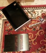
Well the chassis for the pre-amp arrived today, and the caps for the equalizer section arrived yesterday so the build is on. I'll have to proceed carefully due to challenges I'll not elaborate on, but it won't be as quick as my usual builds.
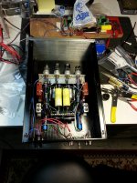
The sockets are mounted on a right angle bracket I fabricated for this purpose eons ago, in fact it is salvaged from a pre-amp I build in 1988. I've punched the locations on the bottom chassis plate for the bracket which is mounted on 1/2" 4-40 standoffs. The bottom plate will be removed for installation of bracket, battery holders, terminal strips and output caps. I will wire it out of box to make like easier.. I will partially wire the sockets as well for the same reason.
The sockets are mounted on a right angle bracket I fabricated for this purpose eons ago, in fact it is salvaged from a pre-amp I build in 1988. I've punched the locations on the bottom chassis plate for the bracket which is mounted on 1/2" 4-40 standoffs. The bottom plate will be removed for installation of bracket, battery holders, terminal strips and output caps. I will wire it out of box to make like easier..
I will partially wire the sockets as well for the same reason.Attachments
Muscovite Mini Build
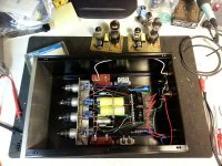
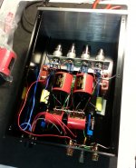
Over the past two days I built a full stereo version of the Muscovite Mini in a rather nice Chinese made chassis box that I bought on eBay for the purpose.
I went with all Russian capacitors in the EQ and for coupling, supply decoupling and screen decoupling caps are of western origin.
I was reminded of how important it is to keep things close and compact when using high transconductance tubes. I had serious oscillation problems in the second stage due to the arrangement of plate load resistors, output wiring, and the plate stopper resistors. I fixed this as I debugged and will post further details when I next work on the unit.
I've ordered another chassis for the power supply and have decided to go with a stereo power supply very similar to the Muscovite supply, except that I used some spare pc boards I made 10yrs ago to implement the supplies which should make the supply build easier. (I have neither the artwork nor spare boards.)
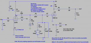
There is an updated schematic reflecting some further, but minor changes which accurately reflect how I built this one.
I'm quite pleased with the overall performance despite the excessive input level (33x transformers with a GM E II) and the power supply which is not really up to the task with ripple and broadband noise in the range of 1.2mV, the filament supply is much worse with 17mV of ripple and noise present on its output.
The sound is very detailed, and the presentation dynamic, HF extension is very good, percussive transients are rendered about as well as I have heard from vinyl, and it images well. Gain between channels is well matched (I've not measured it) with bogey 6Z9P-EV installed. I did grade them for transconductance range, but these are not matched. So not quite the problem I expected.
This unit was intended as an upgrade for the second and third TT, replacing my older gyrator loaded D3A/5842 design. It clearly (to me at least) is a significant improvement in performance.
Edit 12/24: Revised schematic (added C5 back)
Over the past two days I built a full stereo version of the Muscovite Mini in a rather nice Chinese made chassis box that I bought on eBay for the purpose.
I went with all Russian capacitors in the EQ and for coupling, supply decoupling and screen decoupling caps are of western origin.
I was reminded of how important it is to keep things close and compact when using high transconductance tubes. I had serious oscillation problems in the second stage due to the arrangement of plate load resistors, output wiring, and the plate stopper resistors. I fixed this as I debugged and will post further details when I next work on the unit.
I've ordered another chassis for the power supply and have decided to go with a stereo power supply very similar to the Muscovite supply, except that I used some spare pc boards I made 10yrs ago to implement the supplies which should make the supply build easier. (I have neither the artwork nor spare boards.)
There is an updated schematic reflecting some further, but minor changes which accurately reflect how I built this one.
I'm quite pleased with the overall performance despite the excessive input level (33x transformers with a GM E II) and the power supply which is not really up to the task with ripple and broadband noise in the range of 1.2mV, the filament supply is much worse with 17mV of ripple and noise present on its output.
The sound is very detailed, and the presentation dynamic, HF extension is very good, percussive transients are rendered about as well as I have heard from vinyl, and it images well. Gain between channels is well matched (I've not measured it) with bogey 6Z9P-EV installed. I did grade them for transconductance range, but these are not matched. So not quite the problem I expected.
This unit was intended as an upgrade for the second and third TT, replacing my older gyrator loaded D3A/5842 design. It clearly (to me at least) is a significant improvement in performance.
Edit 12/24: Revised schematic (added C5 back)
Attachments
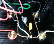
I did some additional rework tonight, I've too many things floating around in there to completely satisfied, but for whatever reason it seems to sound a bit better.
The purpose was to reduce electrostatic coupling into surrounding components and wiring.
The screen bypass capacitors are a little microphonic, and tie wrapping them together to constrain their motion seems to help.
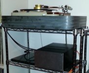
My biggest problem seems to be the UTC - A11 transformers I am using for step up. I experimented with taps and settled on the 200 ohm tap for the primary and left the secondary at 50K, although I did try it with the 50 ohm primary tap and the 12.5K tap on the secondary. It is a lot punchier with the 50 ohm / 50K tap, but the gain is too high, and under extreme conditions there are signs of distress from the transformer.. The cartridge is happier loaded into loads of <100 ohms so this is not optimum. I also have a pair of Partridge 977 with mu metal cores, but their gain is 6X which is insufficient. My Lundahl LL1941are configured for 16X which seems about right with the Muscovite. I could just get a pair of LL1931, the other option would be a pair of Partridge 973A (16X)...
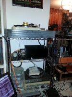
I've listened to both turntables and pre-amps today and this one is definitely holding its own.
The two boards sitting on my bench directly behind the pre-amp are the high voltage regulator modules I mentioned in a previous post.
The purpose was to reduce electrostatic coupling into surrounding components and wiring.
The screen bypass capacitors are a little microphonic, and tie wrapping them together to constrain their motion seems to help.
My biggest problem seems to be the UTC - A11 transformers I am using for step up. I experimented with taps and settled on the 200 ohm tap for the primary and left the secondary at 50K, although I did try it with the 50 ohm primary tap and the 12.5K tap on the secondary. It is a lot punchier with the 50 ohm / 50K tap, but the gain is too high, and under extreme conditions there are signs of distress from the transformer.. The cartridge is happier loaded into loads of <100 ohms so this is not optimum. I also have a pair of Partridge 977 with mu metal cores, but their gain is 6X which is insufficient. My Lundahl LL1941are configured for 16X which seems about right with the Muscovite. I could just get a pair of LL1931, the other option would be a pair of Partridge 973A (16X)...
I've listened to both turntables and pre-amps today and this one is definitely holding its own.
The two boards sitting on my bench directly behind the pre-amp are the high voltage regulator modules I mentioned in a previous post.
Attachments
See this post for the most accurate model: http://www.diyaudio.com/forums/tubes-valves/243950-vacuum-tube-spice-models-9.html (Posts #87 and #88)
Please change the value for kg2 to 400 in order to have reasonably accurate screen currents in simulation..
Alternately you can pull the model from the library I have posted further along in that thread.
Please change the value for kg2 to 400 in order to have reasonably accurate screen currents in simulation..
Alternately you can pull the model from the library I have posted further along in that thread.
Embarrassed to admit I left out the 47K input resistors which of course did not make the SUT that happy.. lol Now fixed..
I now need to address the power supply issue, and also acquire another set of good SUTs for my SPUs. This unit will be used with my second TD-124, and a Garrard 401 when it is finally restored.
I now need to address the power supply issue, and also acquire another set of good SUTs for my SPUs. This unit will be used with my second TD-124, and a Garrard 401 when it is finally restored.
I ended up replacing the MBGCH-1 0.25uF PIO coupling caps with REL TFT 0.22uF/400V teflon coupling caps resulting in a pretty substantial improvement in transparency. These caps are expensive but with care to minimize stray capacitive coupling I suspect the physically huge, but relatively inexpensive Russian FT-3 0.22uF coupling capacitor would work well. I would probably recommend TRT Dynamicaps for the two coupling capacitors in this design, not cheap, but not obscenely priced either - and they are pretty transparent.
Tonight I ordered an AN-0209 (25VA) toroid for the filament supply. The 6.3V filament current is 1.2A so I believe this transformer will be more than adequate with close to a 3A rating at 9V.
I am going to order an XPWR228-120 from Edcor assuming it will fit. (I have one I can use to check for height which is the primary concern.)
Some more minor revisions to improve EMC performance, what I did, and what I might or might not do differently.
I noticed swapping out the pre-pre for my pair of UTC A-11 SUTs that there was rather a lot of odd thumping going on, and after the coupling capacitor swap out when I had the A-11s connected there seemed to be a new buzz.
I removed the MBGCH caps and rearranged things slightly to shorten the plate lead wiring from the 6Z9Ps to the coupling caps.
I also added a 0.01uF ceramic between the audio I/O ground buss and the chassis ground. This completely eliminated the odd microphony around the jacks. When I built the phono stage I ran separate audio connector ground and chassis ground from the mecca ground point on the main ground buss - these wires are fairly long (read inductive) so I added the capacitor from the ground buss to the chassis - arguably and practically speaking it might make as much sense to use a single conductor for chassis and audio ground and tie the chassis to the audio ground by the connectors. Not sure since I usually like to keep the two separate - normally I would make the chassis ground connection directly at the mecca and not through 8" of 16awg wire.. Just one of those details.
Attachments
Not that anyone is paying attention.. lol Tonight I swapped out the power supply bypass caps and the screen bypass caps for Welsh made Clarity Caps (SA) - I was expecting some improvement which is what I got - not earth shattering. Somewhat if not entirely surprised at the audibility of those screen bypass capacitors.
It's a little more transparent. Those are the only changes I made..
Waiting on an order of electrolytics and other odds & ends from digi-key, the transformers and choke from Edcor, and a low dollar regulator PCB from China that will provide regulated DC to the filaments in the audio chassis. (Sorry I am lazy - done enough here already.. )
It's a little more transparent. Those are the only changes I made..
Waiting on an order of electrolytics and other odds & ends from digi-key, the transformers and choke from Edcor, and a low dollar regulator PCB from China that will provide regulated DC to the filaments in the audio chassis. (Sorry I am lazy - done enough here already..
)Attachments
- Status
- This old topic is closed. If you want to reopen this topic, contact a moderator using the "Report Post" button.
- Home
- Source & Line
- Analogue Source
- The Muscovite Mini 6ж9п (6Z9P) Phono Stage