In case somebody has questions about my high octane phono preamp (published in the current Linear Audio issue #6), please feel free to ask here or by pm.
I'll try to be helpful")
It's a minimalist 3 transistor design, so easy to build. Oh and it also sounds great!
I will later also upload the schematic here.
I'll try to be helpful
It's a minimalist 3 transistor design, so easy to build. Oh and it also sounds great!
I will later also upload the schematic here.
schematic
Hi all,
thanks for your interest!
This is the schematic of the high octane phono pre.
Maybe I should have said earlier that it does not comply at all with the current rules of 'good' circuit design:
At least it uses a shunt regulator as power supply
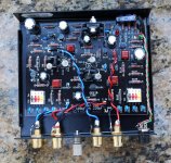
It can be build into a 10x8cm large box.
Hi all,
thanks for your interest!
This is the schematic of the high octane phono pre.
Maybe I should have said earlier that it does not comply at all with the current rules of 'good' circuit design:
- it uses bjts instead of jfets
- active RIAA instead of a passive one
- quite some negative feedback instead of running open loop
At least it uses a shunt regulator as power supply
It can be build into a 10x8cm large box.
Attachments
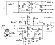
The starting point for this single ended circuit is a 3 transistor circuit from H.P. Walker and dates back to the 60ies. There is some information also in Douglas Self's book on small signal design!
On a side note, the opamp shunt regulator with its excellent performance is originally from Ovidiu (synesthesia) and the particular frequency compensation scheme from Edmond Stuart.
The points denoted as SENSE are for remote sensing used by the shunt regulator, such that the voltage is regulated directly at the first stage!
To aid with building the preamp, the Gerber files with BoM and building tips are now also available; you can find them at
Online Articles
Happy building!
Online Articles
Happy building!
I build this unit myself and use it on an MC with a 1:8 step-up input transformer.
Incredinly as it seems, this 3-transister unit performs as well as the best I've heard!
If your are turned off by phono preamps with dozens of devices that need to be tightly matched and tricky adjustments, this is for you! DIY audio at its best.
Jan
Incredinly as it seems, this 3-transister unit performs as well as the best I've heard!
If your are turned off by phono preamps with dozens of devices that need to be tightly matched and tricky adjustments, this is for you! DIY audio at its best.
Jan
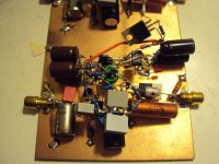
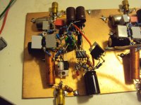
Just for fun i build a P-P version too. Trouble is that i can not persuade the shunt to make the voltage higher then 27 V. I consulted with Jan and i have tried to adjust the sense resistors but no luck so far. Ether i have made a stupid mistake or there is something wrong with the schematic i have. Jans version works so i am at a loss to explain the reason why. I will post a photo.
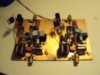
Hi Joachim!
Great point-to-point build!
By the way, did you build the original single ended version first? Did the regulator work then?
Basically, the opamp simply compares the voltage from the LED (a 1.6 V red LED in my case) with the fraction 1/25.5 of the regulated voltage which is again 40V/25.5 ~ 1.6V. Any difference between these two voltages is compensated by adjusting VGS of the shunt mosfet.
When the output voltage never raises up to the intended 40V, please check that you have a 1.6V LED (not an 1.2 V or so) and your two sensing resistors RP2, RP3.
Alternatively, please check total current draw across RP1 and compare it to the one I mention somewhere in the article. I'm sorry I cannot give you the exact value right now as I don't remember the total current draw out of my head.
Hannes
Definitely a tempting little circuit. But is everyone happy with a 50A device in that position? I'd definitely choose something with lower capacitance. I don't mean to be controversial... surely you can see why. I mentioned this to the original designer and he had a fit. Just my 2c.
Just my 2c.- Home
- Source & Line
- Analogue Source
- The high octane phono preamp