This is my go at an external power supply for the SL-1200.
After a conversation with Wayne Colburn of Pass Labs, learning that he has made a few SP-10 PSU for in-house use, a few things became apparent - Get the bridge diodes out of the TT and just have DC on the umbilical. Use 1N4007 diodes, for whatever reason they sound the best, in this case even better than exotic high-speed diodes. Snub the bridge on the AC side with a .22uF film cap. Use multiple stages of RC filtering.
The biggest improvement is of course, no transformer vibration on the platter, easily done merely by locating the transformer outboard of the TT chassis, and this is what I was originally planning to do - but converting umbilical to DC wasn't much more work.
Does it sound good? Of course! And the best part is that I'm not even done yet, the stock regulator hasn't been replaced... (mainly because I ran out of time...)")
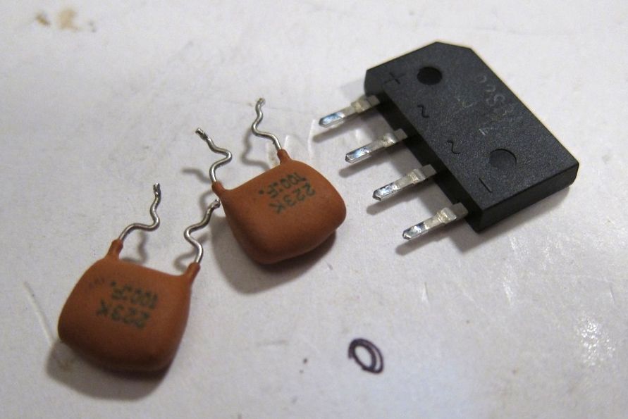
The first thing to be done is remove the bridge diode and snubber caps.
These were located in the holes now visible.
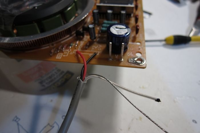
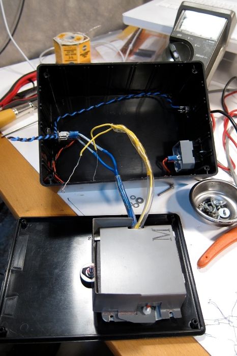
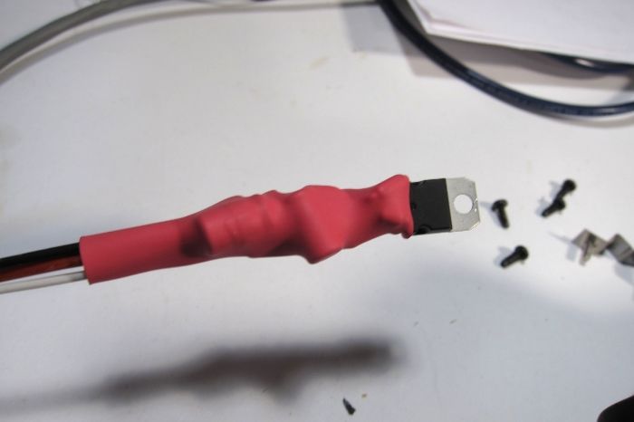
An umbilical is added. The white 3rd wire is capped off, but still there if I need it for something in the future. The bare metal wire is the shield drain, to be attached to ground.
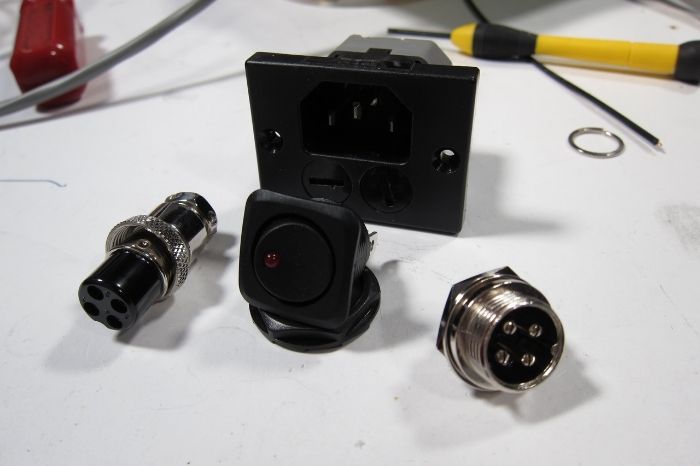
Fused IEC plug, switch, microphone connectors used for the umbilical.
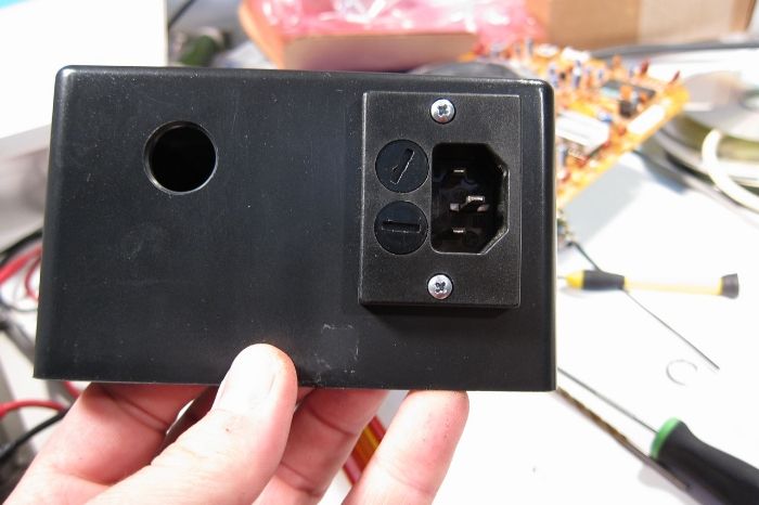
All to be placed into this ABS enclosure.
There is no reason not to use the stock transformer, it's the proper voltage, soft-mounted, has a beautiful mu-metal shield, and is free with the purchase of a turntable.
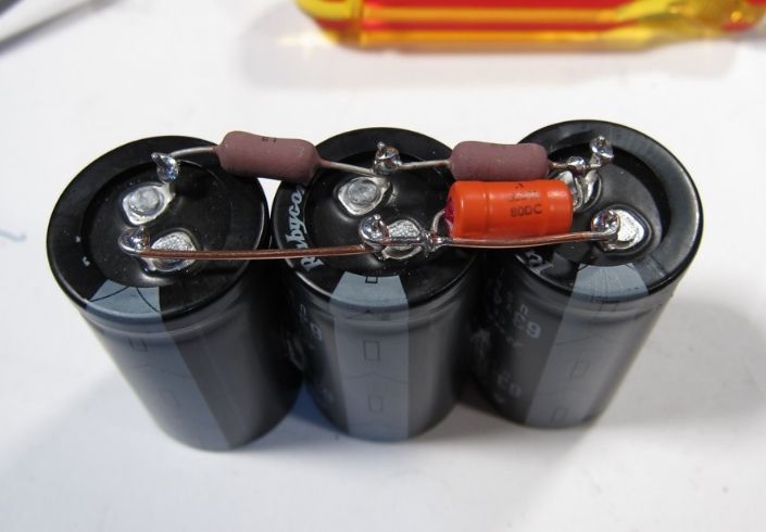
(3) 4700uF 63V volt capacitors, (2) 10ohm 3W resistors, .1uF polypropylene bypass cap, all wired up in a CRCRC filter. Why those values? I had them on hand. If I needed to buy new, I would probably use similar values.
And here it is with the bridge to the side. (The yellow is the transformer secondary.) The eagle-eyed among you will notice the 1K bleeder resistor across the cap bank.
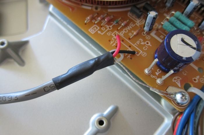
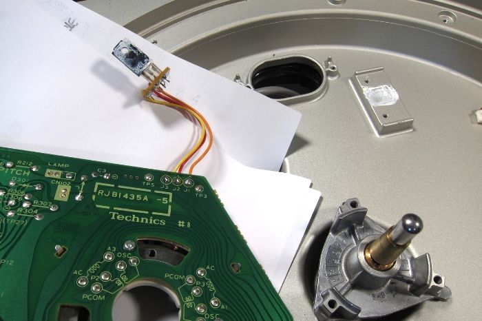
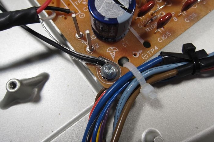
The final configuration of the umbilical attachment to the PCB.
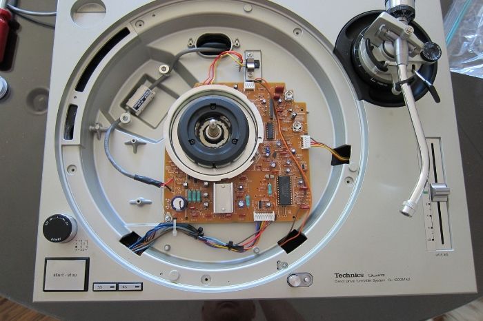
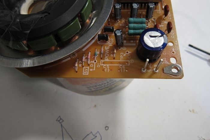
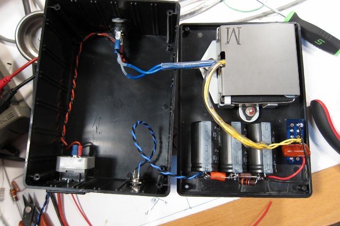
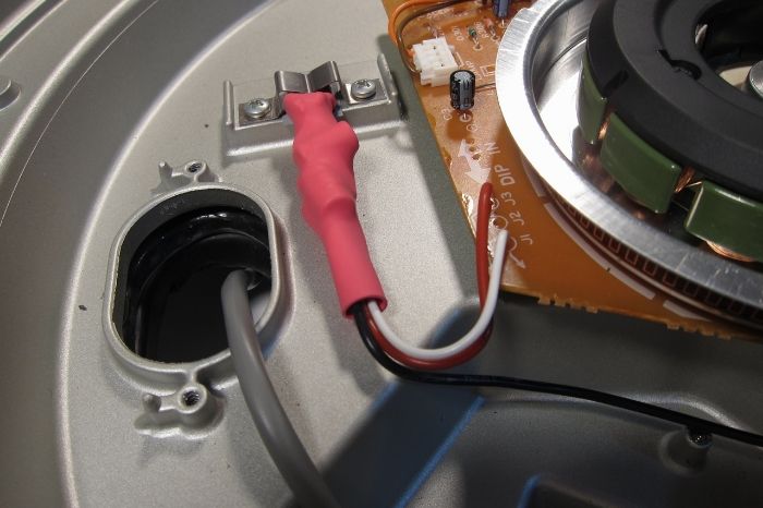
The insides after the modification. I utilized the now unused AC power switch to switch the strobe.
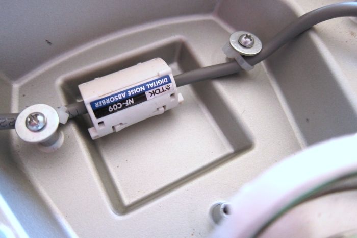
A few zip ties to attach the wire to the studs for strain relief, and of course the obligatory ferrite clamp.
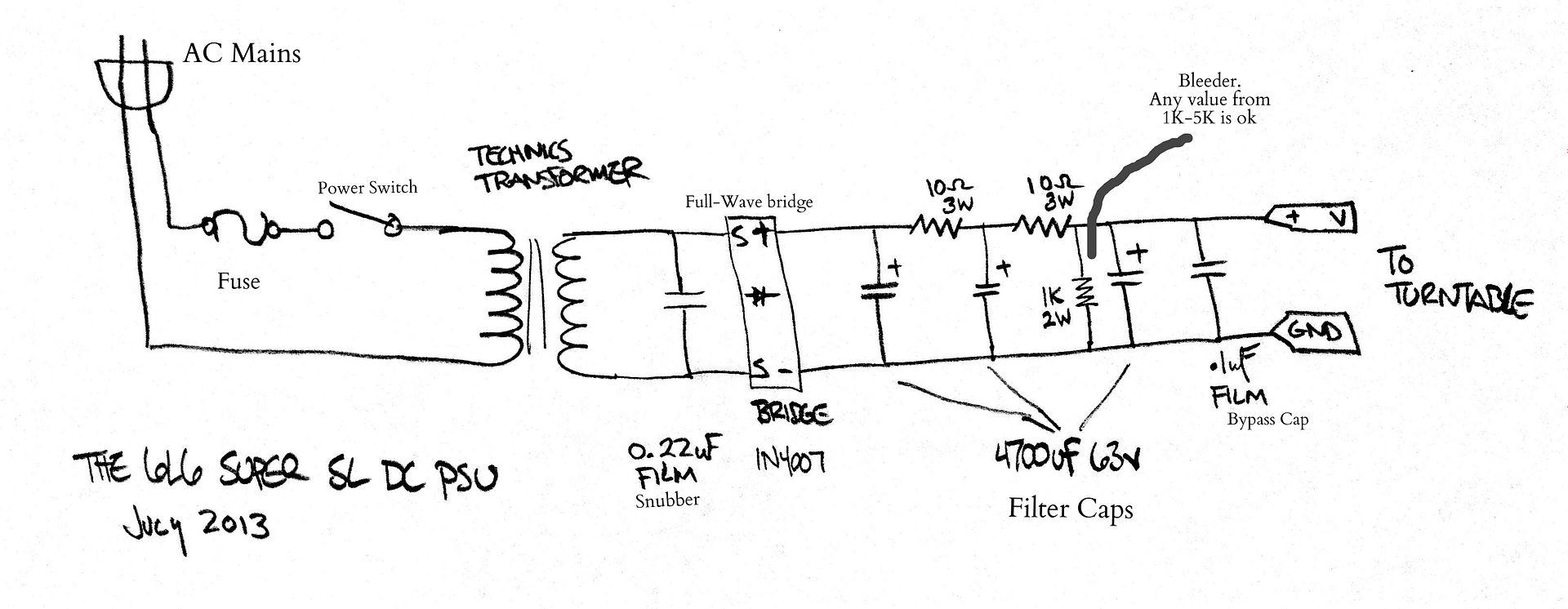
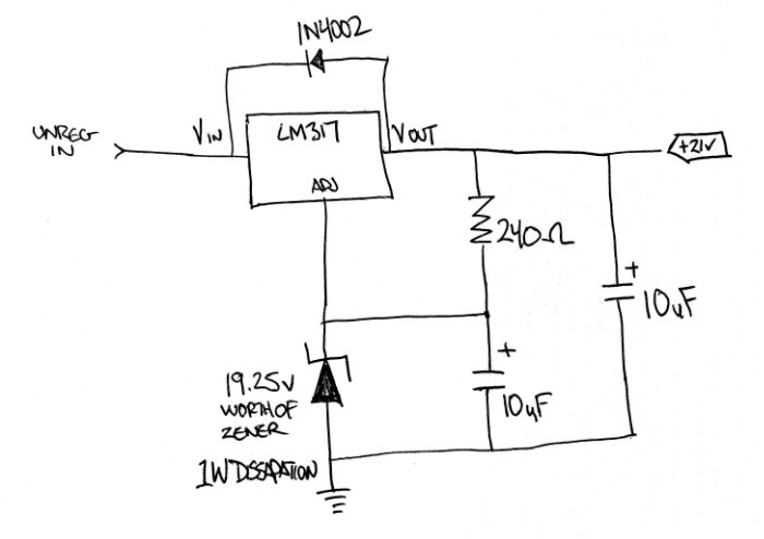
The PSU schematic
This is stage one of my PSU modifications, a different regulator of some sort will be next....
EDIT - and here it is:
After reading this fantastic article - Using 3-pin regulators off-piste: part 1
I have installed the first LM317 based regulator in my SL-1200. There is not a specific schematic in the article, look at the one on page 1 of the 'off-piste' article, and all you do is replace R2 with a Zener reference and make sure you include C2.
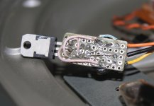
I did mine point-to-point and covered up all in heatshrink as I don't want anybody copying me directly, as it's a point-to-point salad of wire and tape. Do as I say, not as I do and all that...
It works wonderfully, sounds great, and took about 15min to install.
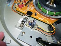
Here it is... not particularly exciting.
Lift the motor PCB and remove the old pass transistor and wires. (You could just cut the old wires and splice if you desire)
It mounts in the same position as the old transistor.
Don't forget some kind of insulator under the regulator - the old transistor was a 'full-pack' and did not need an insulator.
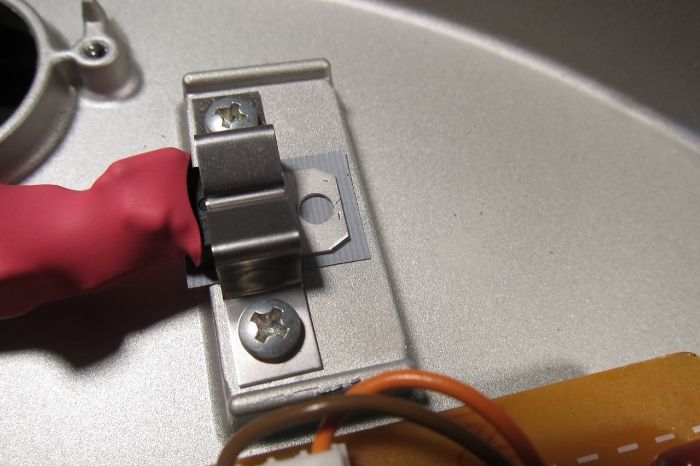
The regulator needs to be grounded here, at the turntable center ground.
Schematic
Questions or comments warmly solicited.
Thank you for looking.
After a conversation with Wayne Colburn of Pass Labs, learning that he has made a few SP-10 PSU for in-house use, a few things became apparent - Get the bridge diodes out of the TT and just have DC on the umbilical. Use 1N4007 diodes, for whatever reason they sound the best, in this case even better than exotic high-speed diodes. Snub the bridge on the AC side with a .22uF film cap. Use multiple stages of RC filtering.
The biggest improvement is of course, no transformer vibration on the platter, easily done merely by locating the transformer outboard of the TT chassis, and this is what I was originally planning to do - but converting umbilical to DC wasn't much more work.
Does it sound good? Of course! And the best part is that I'm not even done yet, the stock regulator hasn't been replaced... (mainly because I ran out of time...)
The first thing to be done is remove the bridge diode and snubber caps.
These were located in the holes now visible.
An umbilical is added. The white 3rd wire is capped off, but still there if I need it for something in the future. The bare metal wire is the shield drain, to be attached to ground.
Fused IEC plug, switch, microphone connectors used for the umbilical.
All to be placed into this ABS enclosure.
There is no reason not to use the stock transformer, it's the proper voltage, soft-mounted, has a beautiful mu-metal shield, and is free with the purchase of a turntable.
(3) 4700uF 63V volt capacitors, (2) 10ohm 3W resistors, .1uF polypropylene bypass cap, all wired up in a CRCRC filter. Why those values? I had them on hand. If I needed to buy new, I would probably use similar values.
And here it is with the bridge to the side. (The yellow is the transformer secondary.) The eagle-eyed among you will notice the 1K bleeder resistor across the cap bank.
The final configuration of the umbilical attachment to the PCB.
The insides after the modification. I utilized the now unused AC power switch to switch the strobe.
A few zip ties to attach the wire to the studs for strain relief, and of course the obligatory ferrite clamp.
The PSU schematic
This is stage one of my PSU modifications, a different regulator of some sort will be next....
EDIT - and here it is:
After reading this fantastic article - Using 3-pin regulators off-piste: part 1
I have installed the first LM317 based regulator in my SL-1200. There is not a specific schematic in the article, look at the one on page 1 of the 'off-piste' article, and all you do is replace R2 with a Zener reference and make sure you include C2.
I did mine point-to-point and covered up all in heatshrink as I don't want anybody copying me directly, as it's a point-to-point salad of wire and tape. Do as I say, not as I do and all that...
It works wonderfully, sounds great, and took about 15min to install.
Here it is... not particularly exciting.
Lift the motor PCB and remove the old pass transistor and wires. (You could just cut the old wires and splice if you desire)
It mounts in the same position as the old transistor.
Don't forget some kind of insulator under the regulator - the old transistor was a 'full-pack' and did not need an insulator.
The regulator needs to be grounded here, at the turntable center ground.
Schematic
Questions or comments warmly solicited.
Thank you for looking.
Last edited:
This is stage one of my PSU modifications, a different regulator of some sort will be next.
I'll be watching for stage #2 with interest. How would you characterize the change/improvement in sound?
jeff
Surely it would be easier and achieve the same result if the transformer alone (30V a/c source), that is apparently noisy, was moved and the electronics left well alone.
Actually the amount of work wasn't that much more to make DC in the PSU.
I agree, however, that the transformer noise is well worth the effort in eliminating but making it off-chassis.
vinylkid58 said:I'll be watching for stage #2 with interest. How would you characterize the change/improvement in sound?
Honestly I haven't listened to it enough to make a detailed analysis. It's absolutely better. I do know immediately that there is less of the darkness that some people find in the SL-1200, and in general the 'get up and boogie' factor is very much increased - I listened to a record I have heard many times before and found myself with goosebumps and dancing. Literally. (It happens to be a disco record, so that's not as odd as you might think... well, the dancing part anyway...)
There is no transformer hum if you place the needle on a stationary record and turn up the volume, so that has to translate into less total noise.
Stage 2 will be very straightforward, once I decide on a bog-standard 317 circuit or something more exotic. I might do both.
I listened to a record I have heard many times before and found myself with goosebumps and dancing. Literally. (It happens to be a disco record, so that's not as odd as you might think... well, the dancing part anyway...)
Not at all odd for me, but then........
jeff
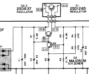
I've done this mod to my 3 MKII and i'm really happy. It sounds better than stock. If you want to keep the light and strobe and still bypass the internal supply including the regulator, remove the wire that leads from the emitter of Q1 to J3, and connect 21VDC at J3. This is how I've done it.
I changed power regulator to classical LM317 circuit as a first step of PSU upgrade, it very simple and took 1 hour. Unfortunately, I didn't make audible comparison, this replace was done right after I bought my 1200Mk2.
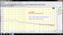
But such upgrade doesn't affect to transformer noise, see second picture - I tested 4 variants (needle in air and on the LP, power On and Off). Obviously 50 and 100 Hz are transmitted via chassis as a mechanical vibration. So, I think that external PSU incl. transformer is absolutely right and necessary upgrade.
But such upgrade doesn't affect to transformer noise, see second picture - I tested 4 variants (needle in air and on the LP, power On and Off). Obviously 50 and 100 Hz are transmitted via chassis as a mechanical vibration. So, I think that external PSU incl. transformer is absolutely right and necessary upgrade.
Attachments
I have had a chance to listen to the turntable enough in the last few days for the sound of the modification to make itself apparent - there is no doubt that the noise floor is lowered, the background is blacker, and the entire presentation is cleaner. But that is the sound...
The startling thing is the musicality - after the mod it is much more difficult to listen to the turntable objectively... I sit down wanting to figure out what the differences sound like, and find myself needing to get up and pick the needle out of the run-out groove after listening to a really great side of an album.
I've done plenty of builds and modifications to lots of equipment over the years. In general the ones where the sonic differences are very obvious are actually not a step forward, although they might sound good. Usually the beneficial mods sound pretty relaxed, in a good way. Nothing stands out. (Although a circuit or the like getting quieter is always beneficial.) The real gains are noticed when you get wonderfully distracted by the music.
Musically this mod is fantastic.
I am not very far into the modification process of the Technics, but I'm quite pleased with how much gain can be made to such a competent deck. It's DNA is pure, and I am very interested into seeing where this adventure leads.
I changed power regulator to classical LM317 circuit as a first step of PSU upgrade, it very simple and took 1 hour.
Khom - Do you by chance have any more photos or a sketch of your perfboard layout you used for the 317 circuit? I would love to make one just like that.
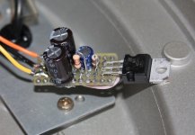
Yes, of course. See attached photos:Khom - Do you by chance have any more photos or a sketch of your perfboard layout you used for the 317 circuit? I would love to make one just like that.
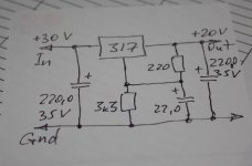
1. Schematic. It's simple datasheet schematic calculated to 20V output DC.
2. and 3. Top and bottom of board, all connections made by parts leads and some additional wires. I didn't created printed board. To connect you can use old YELLOW and ORANGE wires (J1 and J3 - see original schematic 4.), ground wire (BLACK on my pictures) should be added and connected into Tech PCB in any suitable place near power regilator. Do not forget to isolate LM317 from chassis (I used thin mica strip)!
However I still think that the best power solution for Technics is combine of an external PSU with transformer and improved internal regulator like this or something similar.
Attachments

I just found that thread...
It will be tested very shortly
Great!
There is lots more activity on this thread at Art of Sound, a few people have already done this mod with great results --
SL-1200 DC Power Supply DIY
And if you are interested in more mods to the Technics, I was astounded at how much difference changing the tonearm wires made (I am not a cable guy, but this is incredible...) --
Rewiring SL-1200 Tonearm
Yep I have changed my cabling to single run from cartridge to RCA with cardas litz about 2 years ago and never looked back.
But these days I am flirting with the idea of trying a medical grade twinax silver cable I am currently using as interconnect with excellent results...
Edit: I just checked your other thread.
Advice for your next step in wiring. Lose the pcb and run a single run of litz from the headshell to the RCAs. And if you use only one cartridge, I would also advise removing the pins from the arm's end and headshell so that there are nice holes there, and run a single run from cartridge to the RCAs.
Last edited:
- Home
- Source & Line
- Analogue Source
- Technics SL-1200 DC Power Supply