After numerous variations, the easiest to make and the best sounding variation, two balls on the front rail and a roller on the rear rail.
Hi Alex, have you tried linking the rails and damping them, Linking can give you more stiffness for little weight and some quite light damping might stop them ringing to good effect (maybe a strip of sticky back felt or so?)
on my experiments i can see the results of this sort of work on the sidebands of the plots.
M


Mike, I will be looking into this in the near future.
My recently completed Stainless steel tube rails are the lowest resistance i have achieved, better than anodised and more consistent. They wont work for you because your rails are on the mobile part and the weight wont work there (I believe!).
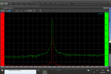
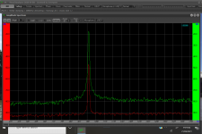
However they give me a nice stiff rail set and the opportunity for simple damping internally. i will try a few different types at some point, but you can see how it tightens in the base of the signal response in the measurements, 638 before, 645 after. the spike is also narrower, can someone more expert than i explain what that is showing please?
Mike
Attachments
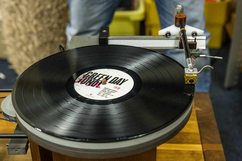
A first prototype arm, rolling on two balls in a V groove...
Very nicely following an excentric record.
Not yet wired and auditioned but just a raw set up to check tracking.
Promising...
proto tangentiale pickup arm - YouTube
Very nicely following an excentric record.
Not yet wired and auditioned but just a raw set up to check tracking.
Promising...
proto tangentiale pickup arm - YouTube
A first prototype arm, rolling on two balls in a V groove...
Very nicely following an excentric record.
Not yet wired and auditioned but just a raw set up to check tracking.
Promising...
proto tangentiale pickup arm - YouTube
Hey, good to see, i think i see steel bearings, have a go with ceramic. when it comes to wiring go straight to Niffys proven solution, happily borrowed by the rest of us, then get listening to a great experience.
Folks on here taught me about listening, measuring and improving and i am sure you will enjoy the same route, what's your background, physics, audio etc, how did you get to here?
M
The balls roll in anodized aluminium grooves; these are anti slip staircase profiles.
Tubes are carbon fibre.
Nice thing is that the bearing point is positioned much lower than most constructions I see here which should be better for VTA.
Now that it is clear that the principle works well I can focus on materials, base construction, wiring and so on.
Tubes are carbon fibre.
Nice thing is that the bearing point is positioned much lower than most constructions I see here which should be better for VTA.
Now that it is clear that the principle works well I can focus on materials, base construction, wiring and so on.
@daanve, Looking at the video I see CL deflection. CL deflection will cause a smearing of the audio as well as wandering image. If I were you this is the first area to concentrate on fixing. The carriage needs low starting torque and low enough Inertia to prevent carriage overshoot.
No idea what you mean with CL deflection...
He will be thinking cantilever deflection, which results from the force necessary to start and move the carriage is too high. Folk on this thread helped me get to a reasonably low friction set up i now have.
After lots of trial and error I am now using two 8mm stainless steel tubes as runners, flattened/straightened and highly polished as a low cost hard flat runner, ceramic 6mm balls and anodised aluminium carriage. that gives the best, lowest starting resistance, and rolling resistance that i have measured so far. The tubes are glued together and rigid and damped inside which improves the measurements as well.
M
Thanks Mike56, got it with the cantilever deflection.
Please note this is a very first set up to check with an excentric record, and it is quite encouraging.
I am sure I will follow the same path with minimizing torque and friction as much as possible.
IMO the strength and elegance of the construction is it's simplicity and low positioned point of flexing (VTA).
Mass of the complete arm/catridge is nicely lowish at 36 grams.
Last edited:
He will be thinking cantilever deflection, which results from the force necessary to start and move the carriage is too high.
Thank you!! I google searched high and low for what "CL deflection" means yesterday but not once in all the posts ever defined "CL" as cantilever. For us in the peanut gallery, it's best to spell out the actual word so we don't have to deal with this alphabet soup.
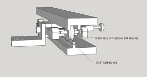
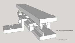
Personally, I think the ball rails have just too high friction and are not easy to control the movements of the balls. Although I highly recommend Niffy's design, I am not satisfied with the rail design. Here is a design idea. I probably will never go back to mechanical linear arms, but I will be glad if my idea may help. The proposal is highly DIYable.
My advice for anyone who wants to build a mechanical linear arm is that sticking to the basic, put all your effect into the rail design. Your first and last goal is to reduce the friction of the rail.
My advice for anyone who wants to build a mechanical linear arm is that sticking to the basic, put all your effect into the rail design. Your first and last goal is to reduce the friction of the rail.
Attachments
Last edited:
Friction can be optimized by using the right materials; please explain why friction is higher than whatever ball bearing?
Balls run (roll) in their V groove in a very controlled manner; they perfectly travel halve the distance the stylus does.
Sliding the arm back after tracking a side, the balls perfectly return (roll back) in their start position.
Balls run (roll) in their V groove in a very controlled manner; they perfectly travel halve the distance the stylus does.
Sliding the arm back after tracking a side, the balls perfectly return (roll back) in their start position.
Here is a design idea. I probably will never go back to mechanical linear arms, but I will be glad if my idea may help. The proposal is highly DIYable.

Very nice design, Jim. I particularly like the repurposing of the outer race of a V-groove bearing. It reminds me of a Schroder diy arm that he repurposed the inner race of a ball bearing on an angular track, sort of the opposite or upside-down of yours. I might have to borrow your idea!
Here is a design idea. I probably will never go back to mechanical linear arms, but I will be glad if my idea may help. The proposal is highly DIYable.
Very nice design, Jim. I particularly like the repurposing of the outer race of a V-groove bearing. It reminds me of a Schroder diy arm that he repurposed the inner race of a ball bearing on an angular track, sort of the opposite or upside-down of yours. I might have to borrow your idea!
Great to see these inputs.
I expect there are many good ways to achieve good results from LTA's.
I started with single rails and BB's, found these unsatisfactory in terms of resistance and found non recirculating balls (NRB) better. However before i tried the NRB solutions i was also sceptical, it was only when i tried it physically and got a feel for it i began to believe this is a better solution.
All ideas borrowed from the threads here!
I expect it may be done either way, however the comment that lowest resistance is king is, in my experience, absolutely true. i have measured at least a 30% lower resistance with two rails and NRB compared to any configuration of rails and BB's, so for now that is my preferred solution.
I have posted vids showing negligible cantilever deflection with NRB's that confirms that solution.
However there are clearly others available, the difference is that solutions like SS tube rails, ceramic balls and anodised cart rails can be executed for ~£50 and some work, whereas other solutions require expensive materials.
It may be a strange reasoning, but building something inexpensive is also a diy'er pleasure.
To repeat, its great to see input from knowledgeable threaders.
BTW, who has some great measurements, pictures or anecdotes to post to show the results of their endeavours?
M
Sorry about the alphabet soup, I'll use proper words....
Firstly lets get a few things clarified for those that are just starting on this journey.
Keep in mind every single tonearm is a compromise and you need to decide which compromises you are willing to live with. Pivoting arms have skating forces and larger tracking errors, Mechanical linear trackers have very flat ellipsoid of inertia, meaning they do not move left right with the same inertia as up down and potential noise in the rail, Servo linear trackers have noise from a motor and rail to deal with and are more complex to design.
The modulation in an LP groove is microscopic. A heavily modulated track could be 60um (microns) and the fine details less than a micron. To put this in perspective an average human hair is about 80um.
If we want to retrieve the micro detail that is cut on an LP, attention to detail is a must, every single micro vibration will smear that fine detail. When you can hear pre-echo on almost every single LP you have just about made it.
The balls/bearings need friction to roll, without friction they would slide on the rail like ice on ice. What is needed is a very smooth surface on the balls and rail so that there is no micro stiction or vibration from the roughness.
Low inertia is needed meaning a carriage that is not too heavy. The higher the inertia the longer it takes for the carriage to stop and change direction on an eccentric LP, and lets face it NO LP is perfectly centered. This effects ALL mechanical linear tracking arms, some more than others, what it causes is chaotic (remember microscopic) horizontal movement.
Remember classical physics, ensure the arm you design/build follows the laws of physics and you will be on your way to a better than good tonearm.
Initially, I used a carbide triangle in the design, but I could not find it. A carbide triangle may not be DIY-friendly. If it is a triangle rail, it is even better because it acts like there are two moving pivot bearings. There are only two contact points.
I would like to control its mass around 60 grams and would recommend anyone who wants to build this arm to use jewel bearings. Jewel bearings are not too expensive. However, if anyone doesn't want to pay for jewel bearings, there is an alternative. I found that cup-point set screws may be used as the vee-cup of jewel bearing, too. Hard drywall screws may be used as pivots.
In order to reduce the mass and to make the arm even simpler, the socket screw for adjusting azimuth may be eliminated. In my experience, I almost never adjust azimuth on mechanical linear arms before and air-bearing arms now.
Attachments
Azimuth adjustment is important in line contact styli, the longer the contact the more critical it is. Conical does not matter and Elliptical not so critical.
My Stanton 880s runs a Fritz Gyger Signature diamond 5x120um channel separation measures 39dB +- 0.5dB each channel. It's currently in my EPA100, being a removable headshell there is a very small amount of play in the collet, if the headshell is held CCW before tightening I get a 15dB difference between channels in separation.
If the arm has no azimuth adjustment shimming is tedious but pays dividends.
- Home
- Source & Line
- Analogue Source
- DIY linear tonearm