Hello Mike56,
Anodized aluminum is a good way to go if the tool marks on the surface of the aluminum rail were oriented parallel to the direction of travel of the carriage, prior to anodizing. In the US, machinists refer to that as "lay"
Sincerely,
Ralf
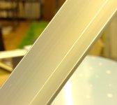
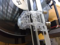
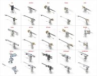
Ralf and All, i took a picture of my 1/2 " aluminium anodised angle and cropped it quite close, if you zoom on this you can see the mountains the poor ball is rolling over. if i polish this flat somehow will i go through the coating?
M
Attachments
Hi Mike,
To test arm / cart resonance, HFN test LP has resonant frequency test tracks on side B. If you don't have that LP then pink noise will also identify arm / cart resonance.
The test tracks are easy as you can hear it. Pink noise you would need to use your spectrum analyser.
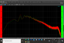
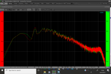
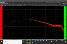
Hi Warren, as you know, although i can operate some of it i do not really knowing what i am doing with S.A , so i played the pink noise track and took a screen shot as attached.
First, i must say i have been chasing the 23 something Hz peak before and have discounted it being resonance of the cartridge end because i added 3.5g to the cartridge end and rebalanced to suit and with the 1khz test tone made no difference.
I probably need to do more tests, could you kindly guide me.
Given the weights and sizes recently posted i dont think that 23Hz is fundamental resonance, much more likely up where yours and Niffys are?
thanks
Mike
Attachments


Ralf and All, i took a picture of my 1/2 " aluminium anodised angle and cropped it quite close, if you zoom on this you can see the mountains the poor ball is rolling over. if i polish this flat somehow will i go through the coating?
M
Typically anodizing is about 0.0005" - 0.0010" thick so you would end up polishing through it.
As an FYI about 1/2 of the thickness of the anodizing actually penetrates into the aluminum.
Scott
Hi, Mike,
From your pink noise plot, I think the resonant frequency is about 21-22 Hz. Here are two plots I did a while ago on my air-bearing arm. One is for vertical and another is for lateral.
Jim
Hi Jim, many thanks. i think i mentioned before i had wondered about that and found in tap tests i could excite that frequency as well, but i concluded that was the part i was tapping resonating, maybe i was wrong. I then added equal mass each side of the pivot to maintain VTF, maybe that doesn't affect resonant frequency? i can quite easily add CW mass at a shorter radius, and maintain VTF that way, i will try that and do a plot to see.
My pink noise band doesn't mention vertical or lateral............
Mike
Typically anodizing is about 0.0005" - 0.0010" thick so you would end up polishing through it.
As an FYI about 1/2 of the thickness of the anodizing actually penetrates into the aluminum.
Scott
Hi Scott, many thanks for the info, that's not going to work then! - i may be worrying about nothing here........
if it turns into a problem i wonder what surface might be used that is hard and smooth,
Mike
Hi, Mike,
From your pink noise plot, I think the resonant frequency is about 21-22 Hz. Here are two plots I did a while ago on my air-bearing arm. One is for vertical and another is for lateral.
Jim
Hi Jim, the top plate carried 2 CW weights, each of 2.5grammes at a radius of 26mm, i added two more of equal weight and halved the radius to 13mm, rechecked VTF, same as before and measured again.
Before is SS424, after SS 425, it doesn't seem to have touched the peak, but filled the dip...........
the bottom plate requires a bit more work but can be done if my design team think its going in the correct direction...........
M
Attachments

Hi Scott, many thanks for the info, that's not going to work then! - i may be worrying about nothing here........
if it turns into a problem i wonder what surface might be used that is hard and smooth,
Mike
Mike,
There is a hard anodizing that can be done I'm not sure if it's available on all colors. I have had pieces hard anodized black.
You could remove the current anodizing with spray on oven cleaner, polish up the surfaces and then have it hard anodized.
Scott
Mike,
There is a hard anodizing that can be done I'm not sure if it's available on all colors. I have had pieces hard anodized black.
You could remove the current anodizing with spray on oven cleaner, polish up the surfaces and then have it hard anodized.
Scott
Thanks Scott, i am going to measure the friction soon and work out if this is a problem or not!!
Then i will consider what to do after that, mike
Hi Mike I think Jim is most likely correct and your arm / cart resonance is 20Hz, You can try adding some weight to the cartridge and see if the 20Hz moves, This will confirm if it is arm / cart or something else.
Work on 1 thing at a time otherwise you could run into the issue of not knowing what solved what issue. If I were you I would work on lowering arm / cart resonance.
Work on 1 thing at a time otherwise you could run into the issue of not knowing what solved what issue. If I were you I would work on lowering arm / cart resonance.
Hi Mike I think Jim is most likely correct and your arm / cart resonance is 20Hz, You can try adding some weight to the cartridge and see if the 20Hz moves, This will confirm if it is arm / cart or something else.
Work on 1 thing at a time otherwise you could run into the issue of not knowing what solved what issue. If I were you I would work on lowering arm / cart resonance.
Thanks Warren, i shall do that experiment, the difficulty i have sometimes is that having a "lightweight" understanding and not knowing what i don't know i can make illogical deductions.
So, say i add 3g on the cartridge side, which is easy, do i balance that by increasing the radius on the existing weights or add weight on the CW side and at what radius etc..........
Its all easy experiments with blu tac in hand anyway
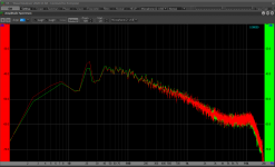
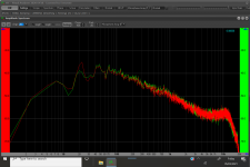
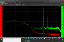
Gents i added 4grms to the cartridge front mounting plate and re-set VTf as before with the CW adjustments. picture attached
Before is 425, after 429 attached.
The 20-23 Hz peak seems to me to stay resolutely where it is.
Before i did this i took screen shot 425, and after 429
it seems to me the 20-23 peak stays resolutely where it is and the hump below moves down from 10 Hz.......
Before is 425, after 429 attached.
The 20-23 Hz peak seems to me to stay resolutely where it is.
Before i did this i took screen shot 425, and after 429
it seems to me the 20-23 peak stays resolutely where it is and the hump below moves down from 10 Hz.......
Attachments
Gents i added 4grms to the cartridge front mounting plate and re-set VTf as before with the CW adjustments. picture attached
Before is 425, after 429 attached.
The 20-23 Hz peak seems to me to stay resolutely where it is.
Before i did this i took screen shot 425, and after 429
it seems to me the 20-23 peak stays resolutely where it is and the hump below moves down from 10 Hz.......
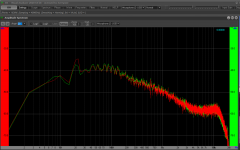
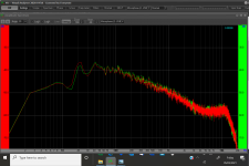
Applying mikes form of logic i then removed 2grms of that added 4 and rebalanced VTF and expected to see the hump in between 5 and 10 Hz, SS 430 attached seems to confirm that.
If that is correct i can play with the top plate and achieve a resonant frequency of choice.
I now wonder about the bottom plate of the paralelogram as well. it may be the nature of the parallelogram means i have differing resonances on the two CW pivot plates. i can then perhaps choose where to put them and whether they should differ........
Attachments
Gents i added 4grms to the cartridge front mounting plate and re-set VTf as before with the CW adjustments. picture attached
Before is 425, after 429 attached.
The 20-23 Hz peak seems to me to stay resolutely where it is.
Before i did this i took screen shot 425, and after 429
it seems to me the 20-23 peak stays resolutely where it is and the hump below moves down from 10 Hz.......
What software are you using and where can it be downloaded? Are there any YouTube videos about it and of how to use it?
Great work on your arm Mike
Continuing with that logic, with 2grms on the cartridge side balanced by longer levers rather than additional weight on the lower plate i see reduced amplitude of what i now take to be a resonance but no change in its frequency. please see 433 attachedApplying mikes form of logic i then removed 2grms of that added 4 and rebalanced VTF and expected to see the hump in between 5 and 10 Hz, SS 430 attached seems to confirm that.
If that is correct i can play with the top plate and achieve a resonant frequency of choice.
I now wonder about the bottom plate of the paralelogram as well. it may be the nature of the parallelogram means i have differing resonances on the two CW pivot plates. i can then perhaps choose where to put them and whether they should differ........
I will be interested in anyone's view of what is happening.
Mike
Attachments
Hi Carl, i was introduced to Visual Analyser by a friend. he kindly guided me through it with a tutorial to start with and gives feedback. Other people on the thread use similar tools and have also been kind enough to guide me.What software are you using and where can it be downloaded? Are there any YouTube videos about it and of how to use it?
Great work on your arm Mike
Some of them really know what they are doing, and are kind enough to guide me, all i can do is take some shots under guidance and look for advice!
To find VA, just google and download a single set up file of the latest and you will be on your way.
mike
Hi, Mike,
From your pink noise plot, I think the resonant frequency is about 21-22 Hz. Here are two plots I did a while ago on my air-bearing arm. One is for vertical and another is for lateral.
Jim
Hi Mike I think Jim is most likely correct and your arm / cart resonance is 20Hz, You can try adding some weight to the cartridge and see if the 20Hz moves, This will confirm if it is arm / cart or something else.
Work on 1 thing at a time otherwise you could run into the issue of not knowing what solved what issue. If I were you I would work on lowering arm / cart resonance.
Thanks again gents, you will see above what i have learnt about the top CWs and resonance, not so much about the lower plate and that i cannot make the 20-23 move......
Previously i had thought from tap tests that both the platter and motor contributed to the 20-23
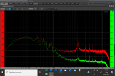
So i stacked every isolation i can (separate plinth with inner tube followed by layers of MLV) under the motor to isolate it from the rest, and got the plots to look like these 442 and 3, pink noise and 444 and 5 the 1khz, both set as i have posted before.
That seems to have a lower noise floor and lowered the 20-23 hz peak.
Interested in your feedback on that if you have a moment
Mike
Attachments

Last edited:
Hi, Mike,
I think the resonant frequency is still about 21-22 Hz although the all-over level is lower now. Can you run a 6-23 Hz sweep once more?
I personally would not advise adding weight to your carriage. First, you may have to add too much weight to move the resonant frequency to a lower position. Secondly, heavier weight may introduce more friction.
As I said before if you don't have too much trouble playing LPs, i.e., not too much mistracking, I would just ignore the resonant frequency.
Jim
to be continued?
One of my pet peeves about tonearms is dealing with the conflict of VTA obsession and its necessity. It would be rewarding to see an invention that can do away with it completely, alas, WITHOUT complexity. (I believe Carlo is onto something and maybe he's cooking something unpublished yet.)
Just imagine an arm moving purely vertically without pivoting: a linear tonearm in its purest form, horizontally AND vertically. (Dd)
I'm sorry to disappoint you, DirectDriver (I owe a lot to your encyclopedic knowledge on TAs, and to your always smart solicitations), but unfortunately I believe, with the corkScrew, that I have reached a cul de sac. Compared to the LilCasey RTA it's an even more radical arm which, instead, brings back some issues of the traditional linear trackers. I.e. too short arm (even if at 90°) i.e. heavy cart with CW on board, i.e. H mass >> V mass.
The clever R&D work by Mike, Koldby and hopefully others, demonstrates how much there is still to be done towards "a linear tonearm in its purest form".
In short, as you can see, maybe I have paid enough my tribute to the cause of TAs experimentation, which convinced me that the pivoted ones still represent the best compromise, and that there is no lack of the possibility of real innovation even there, once deeply understood the implications of Baerwald's work.
good job to all diyers
carlo
Attachments
- Home
- Source & Line
- Analogue Source
- DIY linear tonearm