Hello, Mike
I recommend rearranging the upper counterweight at the bottom of the pipe to avoid the trigger effect.
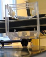
I liked your idea of using balls on the front guide and a roller on the back. The result is a very stable structure that is very easy to move.
I’m giving this for testing tomorrow.
I recommend rearranging the upper counterweight at the bottom of the pipe to avoid the trigger effect.
I liked your idea of using balls on the front guide and a roller on the back. The result is a very stable structure that is very easy to move.
I’m giving this for testing tomorrow.
Attachments
Hello, Mike
I recommend rearranging the upper counterweight at the bottom of the pipe to avoid the trigger effect.
I liked your idea of using balls on the front guide and a roller on the back. The result is a very stable structure that is very easy to move.
I’m giving this for testing tomorrow.
Hi EAlex, please could you kindly explain the trigger effect, i am not familiar, thanks mike
Hello, Mike
I liked your idea of using balls on the front guide and a roller on the back. The result is a very stable structure that is very easy to move.
I’m giving this for testing tomorrow.
Hi Ealex, i did start with the three legged approach but with the places i had the weights, at the end of travel the cart over balanced because the COM (in plan view looking down) went outside the triangle formed by the three points of support. Now i have a suspended secondary rail with 4 balls. Similar but not quite the same.
It will be very interesting to hear how yours works.
M
Recent experiments and developments puzzle me, these confirm that i get better tracking and sound with a lighter counterweight higher and further from the pivot than with heavier, lower and closer, how can that be?
I know the construction needs refinement, but i had to banish bolt and nut counterweights to get rid of the bass grumble caused by their vibration.....amazing, but true.
Any ideas also for a nice counterweight that doesn't need a lathe?
Those attentive to my progress will se lots of stiffening, damping etc which will culminate soon in a new parallelogram.
If that results in an even better sound i will be delighted and amazed
Attachments
Mike,
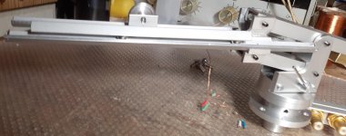
In my first tonearms, the counterweights were placed in tubes and everything was fine, but when I decided to change the design of the counterweight and raised the lower counterweight relative to its axis of rotation, and cut off the upper one completely, it created a problem with downforce. This showed up on the warped records, the tonearm began to take off and lose contact. Then I began to measure the downforce depending on the height and found that with increasing height, the downforce decreases and after passing the dead center, it just took off. I was shocked, the downforce used to increase with increasing lift. In the end, I turned the parallelogram over, the counterweight dropped below the axis of rotation and everything was fine.
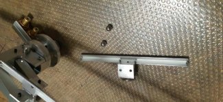
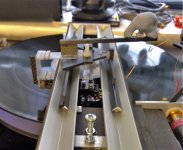
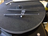
In post 4091 I can see a roller. I also started with the cart rolling on 4 balls of increased diameter of 7 mm, but it is almost impossible to achieve good contact of all 4 balls. One plane can be drawn only through 3 points of support, through 4 points an infinite number can be drawn. On 3 balls, the fulcrum also shifts, and if we put a roller on the back, which stands stable, then we get an excellent 3-point support. The cart design is lighter and the larger diameter balls roll well on anodized corners. The photo shows all this.
In my first tonearms, the counterweights were placed in tubes and everything was fine, but when I decided to change the design of the counterweight and raised the lower counterweight relative to its axis of rotation, and cut off the upper one completely, it created a problem with downforce. This showed up on the warped records, the tonearm began to take off and lose contact. Then I began to measure the downforce depending on the height and found that with increasing height, the downforce decreases and after passing the dead center, it just took off. I was shocked, the downforce used to increase with increasing lift. In the end, I turned the parallelogram over, the counterweight dropped below the axis of rotation and everything was fine.
In post 4091 I can see a roller. I also started with the cart rolling on 4 balls of increased diameter of 7 mm, but it is almost impossible to achieve good contact of all 4 balls. One plane can be drawn only through 3 points of support, through 4 points an infinite number can be drawn. On 3 balls, the fulcrum also shifts, and if we put a roller on the back, which stands stable, then we get an excellent 3-point support. The cart design is lighter and the larger diameter balls roll well on anodized corners. The photo shows all this.

Interesting Eduard, In the photo i see the counterweight lower than the pivot of the top bar of the paralellogram, but also higher than the centre between the two. if all the joints are perfectly tight or pre-strained which they will be naturally, i think (!) that the virtual pivot is in the middle between the bar pivots. Then i think it depends where the centre of mass (COM) of the entire left side of the balance is, in your case this is the rails, carriage, cartridge etc, there is a neutral point where it should not be stable or unstable in balance where the virtual pivot and the mass each side is in line, horizontally. i cannot achieve this geometrically and the left side is below the pivot and i find it only works to play well if the overall mass is centred at the pivot, so the right side has to go high..........Mike,
In the end, I turned the parallelogram over, the counterweight dropped below the axis of rotation and everything was fine.
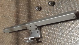
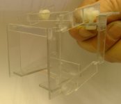
I agree completely about the three points being desirable if one cannot get the tight tolerance that Carlo achieves to get constant 4 ball contact. i started with 3 balls, two on one side, one the other and with all of them progressing separately the COM was going out the triangle or very close causing instability, so my solution that you see in the post is two rails each with two balls but the mobile rail pivots on that bearing, the bearing is not running like a wheel, making it like a 3 legged stool but spreading the contacts out and still using balls that i find give lower friction. In the picture you can see the mobile rail assembly upside down showing how it all works, BTW, have you tried ceramic balls on anodised alloy, much lower friction i found. Your solution will be interesting, there are many ways to make this work!Mike,
In post 4091 I can see a roller. I also started with the cart rolling on 4 balls of increased diameter of 7 mm, but it is almost impossible to achieve good contact of all 4 balls. One plane can be drawn only through 3 points of support, through 4 points an infinite number can be drawn. On 3 balls, the fulcrum also shifts, and if we put a roller on the back, which stands stable, then we get an excellent 3-point support.
Your arrangement seems an interesting combination of what Carlo did with LC, which obviously works well and what i have started doing, it will be very interesting to hear how it works, i worry a bit about the whole mass that the stylus must move, do you know the weight of the mobile parts?Mike,
The cart design is lighter and the larger diameter balls roll well on anodized corners. The photo shows all this.
Has this one played music yet? - enjoyable to see what is going on in this field, thanks
M
Attachments
measures as usual
corkScrew RTA - given the great interest on this arm #4150, (1 post, thanks Mike) almost equal to that for Lil Casey prism (0 post), I was a bit lazier than before, making instead some mods and tuning for the corkscrews mechanism, and listened to it for a long time.
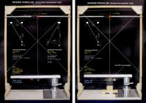
But let's get to the measures, starting with the stiction ones with the Niffy style inverted pendulum. (see attachment)
The horizontal stiction is really interesting, given the considerable weight of this cart (39 gr, cartridge included), = 1,152 mN very close to the 1mN threshold. The measurement of the vertical one looks acceptable, = 2.44 mN: however, it should be noted that since the cartridge is under the rail itself, I had to use a small lever to do the measurement and this makes it less reliable. Perhaps the true data is a little better.
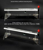
My sine bar measurements of the μ coefficient of friction (friction and stiction) confirm +/- the results of the other. (see attachment) - Measuring both the cart complete with corkscrew (2/3 of the weight!) and naked one (9.5 gr) the results are practically overlapping, almost no difference.
B type corkScrew cart - Total weight = 39 gr
friction - runs with a tilt of a 0,20 height / 300mm rail. angle = 0°2'17" = 0,038 decimal --- μ=0.00066
stiction - starts with a tilt of a 0,45 height / 300mm rail. angle = 0°5'10" = 0,086 decimal --- μ=0.0015
bare horizontal cart - Total weight = 9,5 gr
friction - runs with a tilt of a 0,18 height / 300mm rail. angle = 0°2'2" = 0,034 decimal --- μ=0.0006
stiction - starts with a tilt of a 0,40 height / 300mm rail. angle = 0°4'34" = 0,076 decimal --- μ=0.0013
As said in the presentation, the critical point of this arm is the relationship between the flexibility of the hinge and the two arms with CWs. The holder itself causes noticeable changes even with minimal variations in width and stiffness. I made 3 conceptually different corkscrews, changing several widths of the holder and stiffness of the hinge. Here are the data of the one used for videos.
VTF variations measuring device (see attachment)
warp 0.25mm = 0 var. - 0.5mm warp = 0 var. - warp 0.75mm = 0 var. - warp 1mm = 0.1 var. - warp 1,5mm = 0,4 var. - warp 2mm = 1.1 var. - warp 2,5mm = 1,8 var.
You may note the hinge's "elbow - lever" effect, good on average warps, horrible with horrible ones. (but no worries, look at the video)
I enclose the videos of my crash test (eccentricity 1,5 mm - warp 2 mm - warp 3 mm - eccentricity + warp). Not so bad even on severe warps, compared to others.
Thanks for your attention: I spare you my impressions on sound and other irrelevant details, as usual.
carlo
PS: due measuring difficulties with such minimal frictions all data are an average of repeated tests
corkScrew RTA - given the great interest on this arm #4150, (1 post, thanks Mike) almost equal to that for Lil Casey prism (0 post), I was a bit lazier than before, making instead some mods and tuning for the corkscrews mechanism, and listened to it for a long time.
But let's get to the measures, starting with the stiction ones with the Niffy style inverted pendulum. (see attachment)
The horizontal stiction is really interesting, given the considerable weight of this cart (39 gr, cartridge included), = 1,152 mN very close to the 1mN threshold. The measurement of the vertical one looks acceptable, = 2.44 mN: however, it should be noted that since the cartridge is under the rail itself, I had to use a small lever to do the measurement and this makes it less reliable. Perhaps the true data is a little better.
My sine bar measurements of the μ coefficient of friction (friction and stiction) confirm +/- the results of the other. (see attachment) - Measuring both the cart complete with corkscrew (2/3 of the weight!) and naked one (9.5 gr) the results are practically overlapping, almost no difference.
B type corkScrew cart - Total weight = 39 gr
friction - runs with a tilt of a 0,20 height / 300mm rail. angle = 0°2'17" = 0,038 decimal --- μ=0.00066
stiction - starts with a tilt of a 0,45 height / 300mm rail. angle = 0°5'10" = 0,086 decimal --- μ=0.0015
bare horizontal cart - Total weight = 9,5 gr
friction - runs with a tilt of a 0,18 height / 300mm rail. angle = 0°2'2" = 0,034 decimal --- μ=0.0006
stiction - starts with a tilt of a 0,40 height / 300mm rail. angle = 0°4'34" = 0,076 decimal --- μ=0.0013
As said in the presentation, the critical point of this arm is the relationship between the flexibility of the hinge and the two arms with CWs. The holder itself causes noticeable changes even with minimal variations in width and stiffness. I made 3 conceptually different corkscrews, changing several widths of the holder and stiffness of the hinge. Here are the data of the one used for videos.
VTF variations measuring device (see attachment)
warp 0.25mm = 0 var. - 0.5mm warp = 0 var. - warp 0.75mm = 0 var. - warp 1mm = 0.1 var. - warp 1,5mm = 0,4 var. - warp 2mm = 1.1 var. - warp 2,5mm = 1,8 var.
You may note the hinge's "elbow - lever" effect, good on average warps, horrible with horrible ones. (but no worries, look at the video)
I enclose the videos of my crash test (eccentricity 1,5 mm - warp 2 mm - warp 3 mm - eccentricity + warp). Not so bad even on severe warps, compared to others.
Thanks for your attention: I spare you my impressions on sound and other irrelevant details, as usual.
carlo
PS: due measuring difficulties with such minimal frictions all data are an average of repeated tests
Attachments

Great information Carlo, not surprising perhaps with your care to the measurement techniques ( I think your measurement instruments are better built than my arm!), beautiful build as we always see in your projects and an elegant and simple principle that gives close to the perfect environment for the cartridge to do its work without any undue loads to work against.measures as usual
Measurements to aspire to!
You mention LC prism which i believe is the arm you listen with yourself at home, and although you are not describing the sound on CS, will you now listen at home with CS instead? - Anything you hear that tells you this principle is allowing the cartridge an easier life?
Mike
Now we are almost back in lock down here, there will be attention to some experiments.
Here attached are some pictures of my latest modifications.
The cart remains the same with low friction non recirculation ceramic balls but the warp accomodation has a spread frame to increase stiffness, allow the cartridge to be higher etc, it's still using Mylar hinges.
Reduced bass resonance and surface noise with an appealing detail, tuneful bass etc.
Now this one is working well i hope to build a tidy version
Any one else got some interesting news?
Mike
Attachments
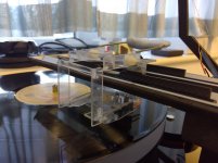
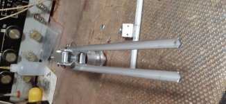
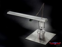
Here is the last version of LC, which is on a turntable. It can be any turntable.
Testing has shown that this version sounds better, has more volume and better localization, better works out the unevenness of the plate. In the video, I put a piece of toothpick under the mat and shifted the center.
Three pivot points ensure stable contact with the guides, and the roller provides a secure footing and does not move off center. By changing the height of the roller axis, we easily adjust the VTA. The cart has become lighter, making it easier to roll. Making this option requires the least amount of work on precision equipment. When manufacturing, I buy suitable profiles from which I remove excess metal.
I will definitely use ceramic balls.
The ingenious idea of CARLO to put a parallelogram on a swivel base and install guides on it, allow making the cart with the cartridge as light as possible.
Attachments
When manufacturing, I buy suitable profiles from which I remove excess metal.
I will definitely use ceramic balls.
Eduard, can you get anodised sections? - they are much harder and smoother than bare extrusions.
There are different tolerance balls, try to get C5 or C3, mine are only 10 but much better than the results i got with Delrin anyway.
M
Thanks an Happy Christmas also to Carlo and everyone else.
It is likely to be pretty quiet so lots of time to think about and execute new ideas!
Mike
Carlo, CS is a very elegant and apparently simple solution (always nice to see that) which deserves much attention from the community.
It is likely to be pretty quiet so lots of time to think about and execute new ideas!
Mike
Carlo, CS is a very elegant and apparently simple solution (always nice to see that) which deserves much attention from the community.
- Home
- Source & Line
- Analogue Source
- DIY linear tonearm