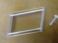
Well, i couldn't resist it either, so out came some aluminium and some Lexan sheet, I filed the notches in the sheet and the points on the aluminium.Couldn't resist: added the spring (well a rubber band) to work as CW, and behaves the same as previously; and another mock up for the first idea - one lever+2 strings - This one seems easier to build and calibrate, (especially the azimuth). Promising, imo.
Ciao bambo, that mock up "nicely illustrates" simply that the upper rope, under normal tracking conditions is under tension, not compressed.
...there is nothing that prevents the collapse of the whole parallelogram construction:
For sure, exactly as any pivoted without a lifter, but from a lower height. Do you usually put lifters on your mock ups? not me
carlo
always nicer that arm, Mike.
the elastic band keeps it together while playing with it.
its roughly the same size as my parallelogram, so i could continue and fit it and you can feel it would work, low friction stable across the plane but i can see it coming to bits and flying all over when setting up etc, i only have one cartridge....and feel it needs always to be firmly attached to something, so for now i will continue to seek out some thinner mylar and see how that way feels. that's an M4 bolt for size
Attachments
Last edited:
Never use a mock up (+ rubber band!) with a real cartridge, even the cheapest in the world!
Mylar: it has to fold with some roundness not on an angle (this will break it), so what about parallelogram geometry?
I've started to think that the inextensible string + one extensible lever (2 small springs to keep it always in touch) may work.
carlo
the cheapest one...
a matter of ethics, not money. The little cartridges, humble companions of our experiments, face a life of sacrifices and dangers with us diyers, too often in absolute silence; sometimes made definitive by our carelessness.
A little respect for their indispensable work, heck
Last edited:
I think the Mylar small bend will be very small and consistent on the 4 corners if i can make it very accurately, but time will tell! At the moment i am struggling to buy the very small amount i need!Never use a mock up (+ rubber band!) with a real cartridge, even the cheapest in the world!
Mylar: it has to fold with some roundness not on an angle (this will break it), so what about parallelogram geometry?
I've started to think that the inextensible string + one extensible lever (2 small springs to keep it always in touch) may work.
carlo
I also like the idea of some retaining mechanism, but cannot think of one that suits the hand tools only man! Perhaps one solid central lever and inextensible string above and below with tensioning/length setting might work.....this mornings scribble attached, mike
Attachments
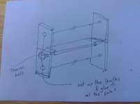
for me better 2 strings around (but just 1 continuos rope) to avoid every possible side torsion. The extensible lever came to mind because the word inextensible doesn't belong to real world, and the blades friction wouldn't increase noticeably.
c
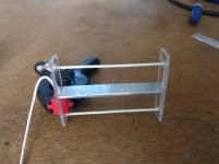
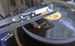
You will recognise some of the parts, just a bit of drilling and filing from yesterday.
This is quite stable to handle, but i think the string is too thick, and although it falls (in warp direction) under its own weight it is much more friction full than yesterdays, however, one can see this is maybe not far off a working idea, would be easy to make and very inexpensive. Tomorrow i will search out some more flexible cord.
I think if the slots are hand filed like mine they, and the knife edge should be longer to avoid play in the VTA direction, alternatively work more accurately. Maybe the end plates in aluminium would work better as well in terms of filing.
I didn't glue the string at the back of the holes yet, this was just an experimental set up, hence the clip remains in place.
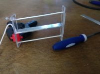
That's about 10mm of movement sat on the handle of the file, mike
Attachments
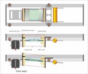
2+2 - 0,25 mm dyneema or spectra string - (4 strings of this diam. may lift a person, and we are dealing with 10 15 grams)
Something like this: the spring lever may be really useful to share equally the loads on the two sides of the parallelogram, much better than rigid lever+ elastic strings. Different tensions drive to uneven vert movement.
ciao carlo
Something like this: the spring lever may be really useful to share equally the loads on the two sides of the parallelogram, much better than rigid lever+ elastic strings. Different tensions drive to uneven vert movement.
ciao carlo
Attachments
I think the Mylar small bend will be very small and consistent on the 4 corners if i can make it very accurately, but time will tell! At the moment i am struggling to buy the very small amount i need!
Very good news - If it folds with the right friction (ie no friction) the mylar solution may be the solution: light, small, cheap, easy to build and without chattering: to be done, and listened - imo
c
Very good news - If it folds with the right friction (ie no friction) the mylar solution may be the solution: light, small, cheap, easy to build and without chattering: to be done, and listened - imo
c
2+2 - 0,25 mm dyneema or spectra string - (4 strings of this diam. may lift a person, and we are dealing with 10 15 grams)
Something like this: the spring lever may be really useful to share equally the loads on the two sides of the parallelogram, much better than rigid lever+ elastic strings. Different tensions drive to uneven vert movement.
ciao carlo
I like more and more this elegant looking little module, its getting simpler all the time which also appeals.
What is the balance between the benefit of reducing the weight without the counterweight and a VTF (perhaps variable) spring across the parallelogram, saving about 30% on this overall weight?
There are constant force tension springs that look nearly small enough and VTF can be set by moving it along a vertical side to change the angle....hence the force. Always remembering this is actually unloading the hinges down to the VTF that's left it should help reduce friction?
I've been busy and have not been able to follow the thread closely but I like what I am seeing in the direction of this thread, thanks to Carlo (again) and Mike, because for years I wanted to see something new in dealing with vertical movement so audiophiles don't have to be obsessed with VTA ad nauseam. A purely vertical bearing would be ideal. The parallelogram idea is one option, although I'm still not comfortable with the microscopic shift in horizontal distance. Since we are using a form of level or pivot anyway, why not making it about 4 inches long so it can hover over to the end of record area while the carriage center is outside of the platter. This way the runway is not hover over the record area, one of my pet-peeves with parallel trackers, so the gliding area can be placed solidly on the plinth area instead of on a cantilevered bridge. I still prefer the carriage rolling method similar to post#3095 by using two V-groove rollers on a horizontal blade. Thanks again for revitalizing my interest!
I was drawn to Carlos work and others on here and that's what interested me enough to have a go, but i don't have the tools to do any machining so its done by hand.I've been busy and have not been able to follow the thread closely but I like what I am seeing in the direction of this thread, thanks to Carlo (again) and Mike,
A month or two back i would have agreed, now i have observed and learnt to keep every lever short and torque avoided. When i built my first, it tracked fine and played ok except it pivoted on the single rail parallel to the groove under the combined influence of stylus drag and warp movement and the varying vertical lever associated with that. Those things are still there and controlled by the second stabiliser rail which of course sees varying loads and causes drag/friction.why not making it about 4 inches long so it can hover over to the end of record area
So now i have learnt what is meant by avoid long levers the hard way and so i shall try and make the current contraption work and then pivot the whole assembly at the base off the platter for record loading, exactly as one does with a pivot tone arm, unless i see a better suggestion first. mike
Many thanks for your input Niffy.Hi Mike,
I think that the problems that you are experiencing with your arm cables is simply due to them being too heavy a gauge. I initially had the same problem with my arm cables. My current arm cables are made from very thin magnet wire. The wire is 0.08mm, which is 40 gauge. I twist 4 strands together then use 2 for the positive and 2 for the negative. This twisted quad had excellent shielding. Each quad is very thin. I run one quad per channel.
I tried using just 2 strands but the sound was a bit thin. I also tried 6 strands. I could not hear any difference between the 4 strand and 6 strand cables but the 6 strand was notably stiffer.
I hope this helps.
Niffy
I couldn't find 40 so mine is 38 gauge, still plenty thin, stranded out like you describe.
Its tricky work at that size isn't it!? - i struggled to get the twist retained.
Anyway the first version is up and running and we've tracked half a dozen records without skipping at all now.
The stiffness of the wire when moved sideways wont move the carriage at all, a massive difference to before.
I rebuilt the carriage to move the stylus up closer to the rail and its sounding good.
Ah yes, sorry about the tape tabs, i don't have any shrink sleeve at the moment!
Next move is to improve the rails, along Carlos lines i think, then to change the parallelogram bearings to remove BB's and reduce side play.
I notice more open cymbals and the like as well as good tuneful bass, a fun project and listen.
Attachments
can't rember if i used Litz-wire-10-46 or
7-44 but it works well for rewiring rms and tins/solder fairly easily.
Might also be
https://www.ebay.de/itm/8-46
regards
james
7-44 but it works well for rewiring rms and tins/solder fairly easily.
Might also be
https://www.ebay.de/itm/8-46
regards
james
can't rember if i used Litz-wire-10-46 or
7-44 but it works well for rewiring rms and tins/solder fairly easily.
Might also be
https://www.ebay.de/itm/8-46
Thanks, i shall keep that one and one day see if i can make a litz harness with little enough stiffness and hear that its better than this magnet wire one. but for now, thanks to Niffy i have a working arm wire.
Do i guess that your rewiring is pivot arms?
regards
james
Great question Warren, at the moment will be either a Knife edge centre strut with light inextensible string stabilisers each side or light mylar micro hinges which i prefer but cannot yet find suitable material, i have 125 micron and i can see how it would be good and stable but needs to be less springy, can only buy a 75m roll of 75 micron, and i need about 5 square centimeters!Great result Mike.
What are planning on replacing the vertical pivot bearings with?
@Mike56 I just received some moisture sensitive parts from Mouser. Those come in Mylar bags. I have no clue how thick this film is, but I could send you the empty bag once I've used the parts. It's way more than 5 square centimeters, but not too much to fit into a regular letter envelope.
@Mike56 I just received some moisture sensitive parts from Mouser. Those come in Mylar bags. I have no clue how thick this film is, but I could send you the empty bag once I've used the parts. It's way more than 5 square centimeters, but not too much to fit into a regular letter envelope.
Many thanks Grufti, i have found someone locally who uses it for model boat sails and i hope will cut me some samples, if that fails i may revert to you if thats ok.
Thanks again
Mike
Hi all,
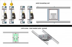
a small step along the mouse trap path (#4007), trying to reduce as possible the levers length, for the concerns explained at #3987. The more i think, the more the axial solution seems more appealing (just to me).
Still toying with my corkscrew cart (here too, I do not like those two arms), but beginning to despair to find a solution: could be something like the one below, but having to go on the moon (1/6 gravity) to listen a record seems rather uncomfortable...
carlo
Attachments
- Home
- Source & Line
- Analogue Source
- DIY linear tonearm