Very nice too Koldby, My gut feel was to remove the rail and carriage bearings weight from that moved by the cartridge, so i like the option with the parallelogram under the carriage, also the small weight there is, is low under the carriage bearings to avoid temptation to capsize and resist stylus drag forces. i also like the orientation of yours as it looks symmetrical but i think simply, i started that way and moved at sketch stage to sideways to avoid warp wow and seem stuck there at the moment. i dont have a feel of the relative forces but feel stylus drag must be quite small? early on for me Warrjon encouraged the build something and see route and i am on that for now.Nice Mike!
I am almost on the same route as you Mike, but maybe it is the wrong road considering the thoughts in #2695 ?.
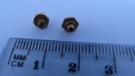
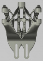
My take on this is two 6 mm carbon rods. The bearings are from some turning coil instruments I had lying around. The pinol screws have a spring loaded seat inside and I made some 1 mm pins from 1 mm drill shafts machined with a point shape that goes through the carbon tubes and into the seats.
Weights less than 5 gr.
I am absolutely not sure , that I have made this with the precision required, but having fun trying...
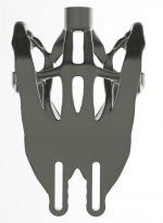
Dimensions in second pic.
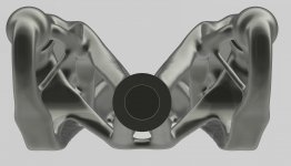
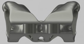
It could be used under the rail, in a passive arm as the third pic, or over the rail as in the two last pics.
In the last example, the supporting structure would be an arm that moved , if the cartridge moved in the short rail.
The last two sketches were made before I actually made the parallelogram, so the dimensions are off.
I dont have useful things lying around so buying in on a budget is more restrictive, i also have only one cartridge to experiment with so comparisons will be more tedious, best, mike
These bearings come from very cheap instruments , like this:Very nice too Koldby, My gut feel was to remove the rail and carriage bearings weight from that moved by the cartridge, so i like the option with the parallelogram under the carriage, also the small weight there is, is low under the carriage bearings to avoid temptation to capsize and resist stylus drag forces. i also like the orientation of yours as it looks symmetrical but i think simply, i started that way and moved at sketch stage to sideways to avoid warp wow and seem stuck there at the moment. i dont have a feel of the relative forces but feel stylus drag must be quite small? early on for me Warrjon encouraged the build something and see route and i am on that for now.
I dont have useful things lying around so buying in on a budget is more restrictive, i also have only one cartridge to experiment with so comparisons will be more tedious, best, mike
Voltmeter SO-45 AC 0-300V Round Analog Dial Panel Meter Voltmeter Gauge Black | eBay
My gut feel was to remove the rail and carriage bearings weight from that moved by the cartridge
Horizontally, the cartridge is still moving the weight of everything, or did you mean something else?
These bearings come from very cheap instruments , like this:
Voltmeter SO-45 AC 0-300V Round Analog Dial Panel Meter Voltmeter Gauge Black | eBay
That sounds like a good idea. Do you have any photographs of the bearing assemblies once removed from the meter movement?
That sounds like a good idea. Do you have any photographs of the bearing assemblies once removed from the meter movement?
Here are the bearings. I made some ø 1mm pins from 1 mm drill bits and made pin point with a Proxxon drill rotating it and at an angel on a bench grinder.
After that polished it on a fine stone still with the Proxxon
Attachments
Good question Apache, what did i mean?Horizontally, the cartridge is still moving the weight of everything, or did you mean something else?
I meant to explain i feel its a good idea (empirical guesswork!) that the vertical movement taken by the parallelogram, if that route is used, is to be moving as little mass as possible, hence better its below the rail............my sketch at 3816 shows that, and i will see if that works, but clearly Carlo already achieved great results another way! - also repeated by others who've built the same.
Others are somewhere in between...........
i don't have the knowledge and experience of many posters, so definite caveat on my ideas!
The main benefit by placing the parallelogram under the rail is that you are not restricted to a lightweight rail construction, thereby you can make it more rigid and , perhaps, with less friction. As I see it anyway.Good question Apache, what did i mean?
I meant to explain i feel its a good idea (empirical guesswork!) that the vertical movement taken by the parallelogram, if that route is used, is to be moving as little mass as possible, hence better its below the rail............my sketch at 3816 shows that, and i will see if that works, but clearly Carlo already achieved great results another way! - also repeated by others who've built the same.
Others are somewhere in between...........
i don't have the knowledge and experience of many posters, so definite caveat on my ideas!
")
I cannot find compliance figures for the Rega Ania i have........just thought the least work the cartridge does in moving things the better?Low vertical mass isn't always good
I guess you've already considered your cartridge compliance in attempting to keep mass low. For me, mass is good!
i agree, but now i am not sure about anything much.....................The main benefit by placing the parallelogram under the rail is that you are not restricted to a lightweight rail construction, thereby you can make it more rigid and , perhaps, with less friction. As I see it anyway.
Here is a great source of jewel bearings / pivots for those making a linear tonearm. I got my bearings from them. USA source. Good luck
https://birdprecision.com/
Joe
https://birdprecision.com/
Joe
Best way to be sure is to try it!
Even Rega don't list the compliance figures for that cart on their website! Odd, as it's pretty important wrt the mass of your arm. Being MC though, I would have thought it will be low to medium compliance.
Here is a great source of jewel bearings / pivots for those making a linear tonearm. I got my bearings from them. USA source. Good luck
Bird Precision
Joe
Thanks for that, i also got a nice response from Dave at Swiss jewel, copied below, i may go the jewel way later!
Thank you for this inquiry- we have a few successful Tonearm customers and they implement our
Sapphire vee-jewels and pivots,
www.swissjewel.com
you can click on products then click on pivot
and then click on jewel bearings, and find “sapphire vee-jewels”
for tonearm gimbal pivots - the radius of the pivot should be 1/3rd less than the radius of the vee jewel – for a frictionless environment.
You can see the prices and buy a al care online
Average prices for vee-jewels and pivots are under $10 per piece with a $5.30 average price unit.
I'm about to experiment with this.
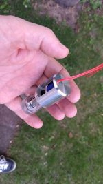
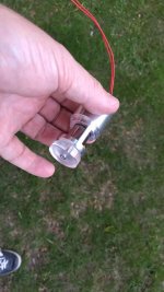
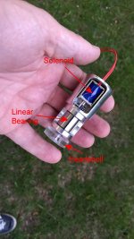
I've been thinking about an electronic way of applying lift / lower, but have got a bit carried away! This is the entire vertical movement part of the arm, using a de-sealed linear bearing, with the rod changed to acrylic so it doesnt carry the mag field to the cartridge. Lift / lower (and possibly tracking force) can be applied by activating the solenoid (probably slugged with a biggish capacitor to avoid rapid ascent and descent.
I'm thinking it may be possibly to apply tracking force by varying the voltage on the solenoid. It's a 6v for 30g pull one, (may not be sufficient but it's what I had around)
I've just put it together as a trial fit (I need to 'loosen' the link between solenoid and acrylic rod as it's a little tight) and just see what range of force I have, and then borrow a gauss meter from work to ensure I don't have too much field at the cartridge position.
Experimental at the moment, but would be neat if it works.
<edit>
Variable tracking force wont be possible with this type of solenoid, as the amount of pole piece inside the coils varies with the position. Duh, should've spotted this. It will require one with the pole piece passing right through and always being within the coils.
Attachments
Last edited:
Best way to be sure is to try it!
Even Rega don't list the compliance figures for that cart on their website! Odd, as it's pretty important wrt the mass of your arm. Being MC though, I would have thought it will be low to medium compliance.
Because Rega expect you to use ALL their gear. I had an Apheta 2 and it was the worst cartridge I have ever had, sold it with less than 20hrs. My current Technics EPC205 with a Jico SAS out performed it in every way.
I suspect the Rega MC'c are very low compliance as I could hear music coming off the tonearm on the RP8/RB808/Apheta 2 from my listening position with the volume turned down.
I'm about to experiment with this.
I've been thinking about an electronic way of applying lift / lower, but have got a bit carried away! This is the entire vertical movement part of the arm, using a de-sealed linear bearing, with the rod changed to acrylic so it doesnt carry the mag field to the cartridge. Lift / lower (and possibly tracking force) can be applied by activating the solenoid (probably slugged with a biggish capacitor to avoid rapid ascent and descent.
I'm thinking it may be possibly to apply tracking force by varying the voltage on the solenoid. It's a 6v for 30g pull one, (may not be sufficient but it's what I had around)
I've just put it together as a trial fit (I need to 'loosen' the link between solenoid and acrylic rod as it's a little tight) and just see what range of force I have, and then borrow a gauss meter from work to ensure I don't have too much field at the cartridge position.
Experimental at the moment, but would be neat if it works.
<edit>
Variable tracking force wont be possible with this type of solenoid, as the amount of pole piece inside the coils varies with the position. Duh, should've spotted this. It will require one with the pole piece passing right through and always being within the coils.
I tried solenoid to do the lift with wireless remote control on my air-bearing arm. However, my application was different from yours. The cartridge picked some noise from the solenoid so I had to give it up although the noise level was very low.
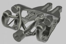
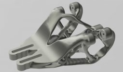
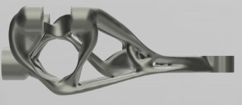
During simulations to measure the truths to a rigid grounding topology for tonearms being superior, I modelled a theoretical carriage with the optimum weight/stiffness, max deflection @ 10 time working load is about 0.5um. Vanishingly small.
Carriage weight ~9g.
I'm not building this as my interest lie elsewhere, just an experiment.
Carriage weight ~9g.
I'm not building this as my interest lie elsewhere, just an experiment.
Attachments
Last edited:
- Home
- Source & Line
- Analogue Source
- DIY linear tonearm