Hi,guys,It is actually a Lil Casey parrallelogram you have placed under the sledge. I have had the same thoughts and it could be a solution.
not only this is not a bad idea,not only it could be a solution, it is just one small step from THE solution! Or should we call it THE arm?
Rpeter
Hi there RPeter, as the key posters/contributors on here well know there will be many trips twixt cup and lip and this may yet be useless, and their own solutions are already excellent........one expects it will have potential because its a collection of some of their best ideas, i am a slow builder but i am collecting the parts, mikeHi,guys,
not only this is not a bad idea,not only it could be a solution, it is just one small step from THE solution! Or should we call it THE arm?
Rpeter
Many thanks again, I have found SMB bearings here and they offer them dry.
Sorry to keep asking, i know i have seen it somewhere, what is the best wiring thought currently please (at reasonable cost)?
This is what I used
Litz Tonearm Rewire Kit 5m | eBay
(2) SRA (Stylus Rake Angle error), in contrast, is both easier to hear and to measure. Perhaps this parameter is pertinent to your investigations. There is also stylus fit to the groove, so you may have to get even deeper into the whole Shibata/Geiger/Jico etc. stylus muck. (Should that be Gyger?).
Andy
Hi Andy,
Yes there are a few things that effect SRA including VTF and VTA. Both the LTA and EPA100 have VTA on the fly so adjusting is easy.
This carriage was made to fit the Stanton and the EPC sits a little low so I need to make a spacer to go between the carriage and cartridge. The EPC does sport a Jico SAS stylus.
There is one other area I am not satisfied with and needs attention and that is repeatable VTF, this is caused by sliding of the wheels on the rail. In my first arm I believe this would be inaudible, but this arm is so revealing any issue is highlighted.
The force that drives the carriage is the longitudinal drag on the stylus. This force is inline with the cantilever.
Hello warrjon,
That force does nothing, as it acts perpendicular to the track upon which the carriage travels.
The force that drives the carriage is, the camming action of the right channel groove flank against the stylus.
Sincerely,
Ralf
Hello warrjon,
That force does nothing, as it acts perpendicular to the track upon which the carriage travels.
The force that drives the carriage is, the camming action of the right channel groove flank against the stylus.
Sincerely,
Ralf
Is there enough load in it to cause the distortion mentioned?
I modified the carriage today. Removed the 3mm thick carbon fibre bottom and installed 2x 0.5mm carbon fibre at 90deg this raised the bottom of the carriage allowing me to lower the VTA, reset the wheels this time with a depth micrometer instead of a ruler. Set the rail up on the granite surface plate and measured the rail and the carriage for straightness the rail was 0.01mm over it's 200mm length but the carriage was 0.1mm which I suspect was due to me removing the polycarbonate grub screw holders and re-installing them.
This time I set the rail level by the front of the cartridge not by a level on the rail. This will have the rail tilting down towards the centre but not enough to cause any issues as I have now played all the problem LP's and so far so good.
Voila - distortion totally gone.
This time I set the rail level by the front of the cartridge not by a level on the rail. This will have the rail tilting down towards the centre but not enough to cause any issues as I have now played all the problem LP's and so far so good.
Voila - distortion totally gone.
Hi Koldby, that's most probably because its most likely a poor idea, however, herewith my sketch and background notes!
mike
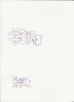
You could even change the direction of the parallelogram like in pic. 1 I think the balance in the hole system will improve.
And instead of the difficult to produce wheel and pin bearings , you could use the suggestion in pic. 2. This straight ball bearing is in fact the basis for the Lil casey rail, described in this thread:
My Linear Tracker (a new variation perhaps?)
By using two rails you avoid the pivoting action of just one rail.
Attachments
I modified the carriage today. Removed the 3mm thick carbon fibre bottom and installed 2x 0.5mm carbon fibre at 90deg this raised the bottom of the carriage allowing me to lower the VTA, reset the wheels this time with a depth micrometer instead of a ruler. Set the rail up on the granite surface plate and measured the rail and the carriage for straightness the rail was 0.01mm over it's 200mm length but the carriage was 0.1mm which I suspect was due to me removing the polycarbonate grub screw holders and re-installing them.
This time I set the rail level by the front of the cartridge not by a level on the rail. This will have the rail tilting down towards the centre but not enough to cause any issues as I have now played all the problem LP's and so far so good.
Voila - distortion totally gone.
Is this with the stanton cartridge?
Niffy
Hi Niffy,
No I could not get the carriage to track successfully with the Stanton, this is with the EPC205 which has about the same compliance as your 2M. I needed to modify the carriage or add a spacer to accommodate the EPC205.
Next plan is to build a servo driven arm with pivots, not sure if I need to start a new thread for that
Sorry to keep asking, i know i have seen it somewhere, what is the best wiring thought currently please (at reasonable cost)?
In the UK, 'The Scientific Wire Company' stock reels of fine Litz at sensible prices.
I am intrigued to know which action improved the distortion, i am edging closer to build and i remember reading about rail slope to centre to provide the move to centre force, is it that or better VTA? - or something else!I modified the carriage today. Removed the 3mm thick carbon fibre bottom and installed 2x 0.5mm carbon fibre at 90deg this raised the bottom of the carriage allowing me to lower the VTA, reset the wheels this time with a depth micrometer instead of a ruler. Set the rail up on the granite surface plate and measured the rail and the carriage for straightness the rail was 0.01mm over it's 200mm length but the carriage was 0.1mm which I suspect was due to me removing the polycarbonate grub screw holders and re-installing them.
This time I set the rail level by the front of the cartridge not by a level on the rail. This will have the rail tilting down towards the centre but not enough to cause any issues as I have now played all the problem LP's and so far so good.
Voila - distortion totally gone.
In the UK, 'The Scientific Wire Company' stock reels of fine Litz at sensible prices.
Excellent thanks, would they do connectors as well?
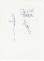
You could even change the direction of the parallelogram like in pic. 1 I think the balance in the hole system will improve.
And instead of the difficult to produce wheel and pin bearings , you could use the suggestion in pic. 2. This straight ball bearing is in fact the basis for the Lil casey rail, described in this thread:
My Linear Tracker (a new variation perhaps?)
By using two rails you avoid the pivoting action of just one rail.
Thanks, I did draw it like that originally Koldby but i thought that keeping the parallelogram movement in line with the rail allowed the stylus to remain centred on the groove in case of warp (hoping the resistance/friction load would be insignificant)whereas the other way there was no automatic compensation and you would get a warp wow, but might not matter.
I am not sure yet how big the con rods etc should be, a sketch might follow as i collect parts and i greatly value input prior to making mistakes.
For me this is a low budget exercise and i have a two ball bearing on borosilicate in mind to start with, aim is <£100 even with most parts being over quantity!
Excellent thanks, would they do connectors as well?
I'm not sure. I had a 50m spool of fine litz from them, but didn't look for connectors. They're not specifically an audio supplier though. If it's cartridge pins you need, find an old D-Type socket and cut it apart.
I'm not sure. I had a 50m spool of fine litz from them, but didn't look for connectors. They're not specifically an audio supplier though. If it's cartridge pins you need, find an old D-Type socket and cut it apart.
Many thanks, i might just go with a few £'s on Amazon but i will check them out first.
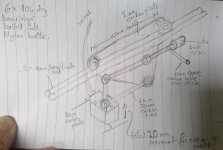
Now i apologise for the sketching, but my "ideas shamelessly borrowed off others" (ISBOO) design currently looks like this attached. Hope its understandable....
Cheap and simple approach but hopefully mostly proven and addressing a good percentage of the important aspects. Cut and glue bits of carbon and bolt on the bearings.
I will do a basic glass tube track and then see how to refine it later.
I haven't done the weights, centres and levers yet, but i think the proportions feel about right?
Please tell me what is obviously wrong with it? - and any suggestions on dimensions much appreciated as well.
Attachments
In the UK, 'The Scientific Wire Company' stock reels of fine Litz at sensible prices.
Hi There Apache, i just checked their site and found myself in the deep end again, i didn't see specific mention of Litz, but now realise that is a generic description and i need to know more detail of sizes etc.
i shall research, any info most welcome as well!
Thanks, I did draw it like that originally Koldby but i thought that keeping the parallelogram movement in line with the rail allowed the stylus to remain centred on the groove in case of warp (hoping the resistance/friction load would be insignificant)whereas the other way there was no automatic compensation and you would get a warp wow, but might not matter.
I am not sure yet how big the con rods etc should be, a sketch might follow as i collect parts and i greatly value input prior to making mistakes.
For me this is a low budget exercise and i have a two ball bearing on borosilicate in mind to start with, aim is <£100 even with most parts being over quantity!
Your arguments is exactly the ones I would use to have the parallelogram in line with the GROOVE as it is in my suggestion . Then you have no sideways movement in the groove, as opposed to having the parallelogram in line with the rail.
Another thing is if you use only one rail, you can get a pivoting movement in the rail, whereas if you use two rails there are no pivot action as in carlos and in my models
But two rails is two lots of friction which seems to have been a major problem.
I don't know the answer! i wish to be minimalist. look forward to other input! mike
Hi Mike,
The issue I see with this design is you have a double vertical pivot. The carriage can pivot on the rail and the cartridge is attached to a vertical pivot. With 4mm rods you will need 3mm wide bearings to sit them at the correct angle on the rail. 6mm rods require 4mm bearings.
To answer your question I suspect the distortion improvement was mainly due to being able to adjust the stylus in the groove afforded by the shallower carriage. Probably more to do with azimuth than VTA. I originally set the rail level and did not worry about checking azimuth as I machined everything to close tolerances. I didn't take into account removing and re-gluing the wheel mounting blocks.
I played quite a few LP's last night and the distortion is significantly better but I can still hear some distortion on the right channel on the inner groove during heavily modulated passages especially female voice. Increasing VTF improved but did not eliminate it. My wife can't hear it but I know it's there.
Tonight's tests will be to adjust the rail which changes azimuth to see if I can completely eradicate the distortion. If this fails I will make another carriage that has azimuth adjustment so the rail can be leveled and azimuth adjusted separately.
- Home
- Source & Line
- Analogue Source
- DIY linear tonearm