Hi Carlo,
Larger wheels will tend to result in lower friction for both of the reasons you suggest. The hertzian strain will be lower. The larger diameter will also ride over imperfections and dust motes more easily.
The reduction in friction isn't just due to the reduced torque at the bearing, although this is a factor. When using a non-recirculating ball bearing, lil casey style, larger balls still result in lower friction even though there is no central bearing element.
Niffy
...Larger wheels will tend to result in lower friction for both of the reasons you suggest ...
Yes Niffy, but is the relevance of their effect that counts.
With our carriage weights (<25gr per wheel), the Hertzian strain (and adhesion too) would remain practically undetectable, on steel as on carbide imho; while the torque to win the bearing's friction is directly multiplied by the radius, and this changes the behavior for sure.
So if I had to make a carriage I would make big wheels with small bearings, as small as possible (eg. vee jewel): that is, I would faithfully copy yours.
...When using a non-recirculating ball bearing, lil casey style, larger balls still result in lower friction even though there is no central bearing element. ...
...The larger diameter will also ride over imperfections and dust motes more easily.
You gave the answer: it's not a matter of friction (as said, no relative motion =0, a grindwheel runs effortlessly even on sand paper) but simply of a lower inclination to lift the mobile masses over the obstacle with such small available forces.
carlo
Last edited:
...Larger wheels will tend to result in lower friction for both of the reasons you suggest ...
Yes Niffy, but is the relevance of their effect that counts.
With our carriage weights (<25gr per wheel), the Hertzian strain (and adhesion too) would remain practically undetectable, on steel as on carbide imho; while the torque to win the bearing's friction is directly multiplied by the radius, and this changes the behavior for sure.
So if I had to make a carriage I would make big wheels with small bearings, as small as possible (eg. vee jewel): that is, I would faithfully copy yours.
...When using a non-recirculating ball bearing, lil casey style, larger balls still result in lower friction even though there is no central bearing element. ...
...The larger diameter will also ride over imperfections and dust motes more easily.
You gave the answer: it's not a matter of friction (as said, no relative motion =0, a grindwheel runs effortlessly even on sand paper) but simply of a lower inclination to lift the mobile masses over the obstacle with such small available forces.
carlo
Hi Carlo,
When I said "Larger wheels will tend to result in lower friction for both of the reasons you suggest." I was using the term friction to describe the total resistance to lateral motion. This includes rolling resistance which, as you correctly pointed out, does not include any relative motion but does resist motion.
When I was using steel wheels on glass rods I thought that the difference in rolling resistance that could be achieved by using harder materials would be negligible and said so publicly on this forum.
Then Joe gave me some tungsten carbide rods to try. Boy did he prove me wrong.
Glass tends to have a very smooth surface, probably a little better than I managed to polish the carbide rods to, so any difference would be entirely due to the difference in hardness (and maybe electrostatic adhesion) and not due to surface finish. Absolutely everything else in the set up was identical. Same wheels, same bearings, same carriage, same mass/load, same test rig and testing method.
The carbide rods resulted in an 18% reduction in the total resistance to lateral motion (fiction). This reduction is not due to a change in the torque required to turn the wheels as the wheels hadn't changed and so nor had their radius. I was surprised by the degree to which the resistance had reduced.
Changing from the steel wheels to the tungsten carbide resulted in a further reduction of 9%. That's a total reduction of 25% compared to steel on glass.
The move to jeweled vees resulted in further significant improvements, reducing total resistance/friction by a further 31%. A total of 48% reduction compared to the original steel on glass with steel pin bearings.
Of the total reduction about half is due to the actual bearing element and half is due to rolling resistance showing that the hardness of the wheels and rails is very important.
Of the remaining friction/resistance I estimate that about 80% is due to rolling resistance. I can't really move to harder materials so the only way to make further reductions would be to make the wheels larger in diameter or make the carriage lighter.
My current jeweled and carbide rail bearing set up has given me a 70% reduction in friction compared to when I was using boca hybrid ballrace bearings on glass rods.
Niffy
Niffy, sorry for possible misunderstanding. I do not doubt the importance of refinements that can be added to a clever project, tested and improved for a long time.
I was just trying to understand how was working the stainless steel ring added by Warrjon to his ball bearings, to find the main reason that transformed an arm with friction problems into a fully satisfactory new one.
The increase in diameter seemed to be a more evident cause than the finishing details: bad workmanship can ruin a good project, while refined materials and processes can lead it to excellence (as in your creations), but will never allow a deficient project to work well.
carlo
Hi Carlo,
As the diameter of the wheel increases the rolling resistance goes down by the square root of the diameter. With the larger diameter wheels the cantilever was deflecting much less, even though I only polished the wheels with 1000grit as I did not have 1500 and 2000.
The Stanton 881s cartridge with Pickering D3000 stylus I am using is very high compliance 30un/nM. Installing the brush also made a difference, the arm now traverses backwards on off center records.
This iteration of the tonearm does not really lend its self to using pin bearings as the arm wand is below the rail. I am gathering the components to make a new arm where the rail will be just above record level. My plan is to make a set of pin bearings from tool steel for the pins and brass for the Vees, wheels will be aluminium and I have bought polished carbide rings.
Hi Niffy,
One thing that has puzzled me is, you measuring a significant drop in rolling resistance between the glass and carbide rods. Were the rods you measured empty?
Rolling resistance (discounting wheel diameter) is due primarily to deformation of either the wheel or rail. An extreme example would be a railway carriage wheel on sand and steel rail.
This would suggest that the glass rods were deforming under the wheels, I would suspect more likely bending. I am wondering if a carbon rod was inserted into the glass and held with epoxy. My reason for this is I have had issues with supply of carbide rods.
Hi Warrjon,
Both the borosilicate glass and tungsten carbide rods are solid. The rods were built into identical support structures as I wanted to be certain that any differences that I measured or, more importantly, heard was entirely down to the difference in rod material. The rail structure consists of a 1mm thick, 19mm wide base plate of tool steel. Along the edges of this base plate run two unidirectional carbon fibre battons, 2mm thick. The channel formed between the battons is where the rods are fitted. On top of the battons are 6mm diameter, thick wall, stainless steel tubes. These are filled with silicone rubber for additional damping. The rail has 10mm thick aluminium end caps bolted and glued to the base plate.
The rails are held together with epoxy adhesive. Each layer was individually glued, clamped and cured in an oven. The clamps not being removed until the rail had cooled to room temperature. This was to prevent warps. Heat curing epoxy massively improves its properties.
The rails are mounted with two M6 bolts at each end. Mounting the rail from both ends makes the whole structure much more rigid.

The rails are very inert and very rigid and just make a dull dump if struck. Dead. Of course the tungsten carbide rail is much heavier.
I don't think the rails will bend enough to be noticeable simply due to the mass of the carriage. It may seem crazy but the difference in rolling resistance is due to the material of the rail deforming under the wheels more with the glass rail. I performed many tests (I made 6 different rails and used many different bearings and wheels) and the results were all consistent with this being the case.
Niffy
Both the borosilicate glass and tungsten carbide rods are solid. The rods were built into identical support structures as I wanted to be certain that any differences that I measured or, more importantly, heard was entirely down to the difference in rod material. The rail structure consists of a 1mm thick, 19mm wide base plate of tool steel. Along the edges of this base plate run two unidirectional carbon fibre battons, 2mm thick. The channel formed between the battons is where the rods are fitted. On top of the battons are 6mm diameter, thick wall, stainless steel tubes. These are filled with silicone rubber for additional damping. The rail has 10mm thick aluminium end caps bolted and glued to the base plate.
The rails are held together with epoxy adhesive. Each layer was individually glued, clamped and cured in an oven. The clamps not being removed until the rail had cooled to room temperature. This was to prevent warps. Heat curing epoxy massively improves its properties.
The rails are mounted with two M6 bolts at each end. Mounting the rail from both ends makes the whole structure much more rigid.
The rails are very inert and very rigid and just make a dull dump if struck. Dead. Of course the tungsten carbide rail is much heavier.
I don't think the rails will bend enough to be noticeable simply due to the mass of the carriage. It may seem crazy but the difference in rolling resistance is due to the material of the rail deforming under the wheels more with the glass rail. I performed many tests (I made 6 different rails and used many different bearings and wheels) and the results were all consistent with this being the case.
Niffy
Last edited:
Hi Niffy,
It suddenly dawned on me, I grabbed the micrometer and measured the borosilicate rods I have and they are not perfectly round or uniform over their length they vary by 0.07mm. Where as the carbide rods I have are within 0.005mm over their length and diameter.
I'll have to buy new carbide rods from a different eBay supplier and hopefully I'll get the ones I ordered this time.
.
Even if they travel on rails with steel wheels, our carriages seem a bit different from locomotives (strangely even the 8,5 gr "Lil Casey" carriage)
just two questions:
has anyone ever measured the strain of a 20x2 mm steel wheel with a load of 25 gr? or at least calculated with the Hertzian formulas - I'm unable
an evenly rough surface has a smaller contact area than a smooth one - is it a disadvantage?
any object in our atmosphere is covered with a super thin film of water - this certainly induces adhesion due surface tension, but how much?
carlo
Brush: Warrjon, this adds a considerable, but difficult to measure, amount of side force to overcome frictions - try again without, please - even better measuring with Niffy's reverse pendulum (a simplified version on # 2574 -2605).
The glass tubes are hot extruded and rolled to measure, not rectified - because for their common uses it's not needed
Even if they travel on rails with steel wheels, our carriages seem a bit different from locomotives
carlo
Brush: Warrjon, this adds a considerable, but difficult to measure, amount of side force to overcome frictions - try again without, please
The physics is exactly the same as locomotive wheels, just the scale is smaller.
After adding the larger wheels I used the arm without the brush on the stylus. The wandering back and forth of the stylus had reduced but not totally eliminated. Adding the brush eliminated the wandering stylus as far as my eyes could see.
It now tracked Marcia Hines which it refused to do before the larger wheels although the arm did not move backwards with off center pressing until I added the brush.
I'm not going to do any more work on this arm as it sounds extremely good. When I build the TT1 style I plan to leverage Niffy's experience to build the rail and carriage. I have ordered all the bits I need, including 4mm carbide rods and 2mm polished carbide rings. I am not going to use jewel bearings I will make my own using brass for the vees and old ejector pins.
.
gadget
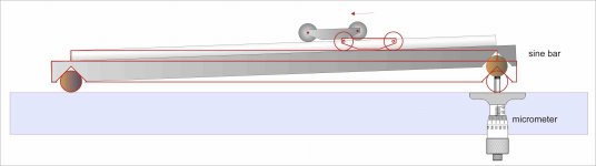
An idea for another measuring system for the carriage friction of an LT. The reverse pendulum works well, but the friction of the string introduces a certain variability, so an average of several measurements must be made.
Rail and carriage are secured to a sine bar (even diy) to measure the critical angle (movement start) with a depth micrometer ...
what do you think about?*
carlo
*this method doesn't consider the shaft lever
Locomotives: yes, same physics - hence the name Lil Casey - just a bit more strain: 10.000 kg on just 200 square mm...
Attachments
That's stress, not strain.Locomotives: yes, same physics - hence the name Lil Casey - just a bit more strain: 10.000 kg on just 200 square mm...
Hi, warrjon
Here is a good source for micro grain carbide rods that Niffy and i use. Good luck.
Carbide Rod – Centennial Carbide: Carbide Blanks, Rod and End Mills
Joe
Here is a good source for micro grain carbide rods that Niffy and i use. Good luck.
Carbide Rod – Centennial Carbide: Carbide Blanks, Rod and End Mills
Joe
Hi Carlo,
The sine bar is an excellent method of measuring friction. When I made my reverse pendulum measuring jig I made it with 3 adjustable feet so that the rail could be leveled. When I initially set up the jig I experimented with tilting the rail to determine friction. It gave pretty much the same results as the pendulum but was much more difficult to make repeated, accurate readings. If I had designed it to use the slope to determine friction in the first place it would probably have been much easier to use. The sine bar could also be used to determine dynamic friction. You tilt the bar until the carriage just keeps moving after being nudged.
Niffy
Hi, warrjon
Here is a good source for micro grain carbide rods that Niffy and i use. Good luck.
Carbide Rod – Centennial Carbide: Carbide Blanks, Rod and End Mills
Joe
Thanks Joe, yesterday I bought another set off eBay from a different seller, the first seller sent me 4x100mm instead of 4x200mm then offered me a discount on a product I'll never use. If I need another set I'll order from above.
cheers
Hi Carlo,
I looked at using hertzian contact geometry to determine rolling resistance. Non of the standard equations describe the situation we have, a torus (the edge of the wheel) resting on a rod (the rail) at a non-normal angle. Deriving the equation for this scenario seemed like far too much work for my rusty maths brain.
I did use hertzian contact equations to work out the energy dissipation of my decks main bearing and derived an amount that matched that found by measurement. It was also useful for determining the maximum contact pressure so that the bearing material would not be over stressed.
I also worked out the contact pressure the pin bearings so that I could choose pin and vee sizes that would survive day to day use.
For contact between simple shapes like spheres, spherical pits, cones and planes hertzian contact geometry can be very useful.
Niffy
Niffy, thanks for all the infos
On my simplified reverse pendulum there was some measurement inconsistency that I had attributed to the sliding of the pendulum string on the carriage while measuring. With the Lil Casey the friction is so low that a good level is not enough for tuning, so I think the angles to be measured would be very small.
By the way I had measured a (small, 20 mg) difference between the first and second one: anodized aluminum better than carbon fiber. the first is harder, but micro porous, the second is mirror finish, but a little less hard. strange
I've studied carefully your rail, really interesting and sophisticated (quote - hot curing is essential). The only thing that still does not convince me is the vertical articulation on the two bars; but things must be tried to know them and you have tried them thoroughly.
What instead seems problematic on Cantus like TAs is the glass tube, not only for the section, as evidenced in my graph, but also because glass tubes are neither truly round, nor straight. and worst, over time - if not well stored on a flat surface - tend to bend: the glass is a liquid, not a solid.
carlo
Those loads on the locomotives come from a paper of an Italian university, which calculates just a 1-2 N rolling friction for every KN load. (things may be eveeen better with our loads...)
The wheel + rail is described as a very refined system, not only for how they realize the differential for curves (this is well known), but more for how it manages the herzian strain, which is sent to the concave S section of the wheel and even more to the axle bending.
Last edited:
- Home
- Source & Line
- Analogue Source
- DIY linear tonearm