reinventing the wheel... as usual
after just a quick googleing.
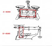
Steelyard were used by romans, maybe long before
Niffy, the VTF variation when the parallelogram is inclined is that given by the small shift of the CG of the CW, as in pivoted ones. Here levers are much shorter and inclinations bigger, but this kind of VTF variation almost undetectable, imho.
Rail leveling instead is crucial, even more than in traditional linear trackers, for the reasons already explained - #3017 last paragraph
carlo
after just a quick googleing.
Steelyard were used by romans, maybe long before
Niffy, the VTF variation when the parallelogram is inclined is that given by the small shift of the CG of the CW, as in pivoted ones. Here levers are much shorter and inclinations bigger, but this kind of VTF variation almost undetectable, imho.
Rail leveling instead is crucial, even more than in traditional linear trackers, for the reasons already explained - #3017 last paragraph
carlo
Attachments
Last edited:
VTA
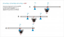
Carlo, your pics are convincing. I'm very glad I didn't promise eating my hat . Maybe while VTF adjusted too high, and left one of the support points starts loosing contact (A) and while carriage travels, both of them renew contact (B) in the middle, and later right one (C) looses it? Seems to be a decent hypothesis...
Anyway, I need to build my own model to experiment with.
Walter
Carlo, your pics are convincing. I'm very glad I didn't promise eating my hat
. Maybe while VTF adjusted too high, and left one of the support points starts loosing contact (A) and while carriage travels, both of them renew contact (B) in the middle, and later right one (C) looses it? Seems to be a decent hypothesis...Anyway, I need to build my own model to experiment with.
Walter
Attachments
Last edited:
Yes, Walter, maybe: but it shoudn't happen with low parallelogram friction and well leveled rail.
Another doubt, a cause of variable VTF could be that the parallelogram is not a real parallelogram. This hinders a truly parallel motion of the rail.
In my drawings I suggested to drill the elements together, in order to get precisely the same distances. Unfortunately such lack of precision has no remedy, because a misalignment proportional to the error will be anyway generated
c
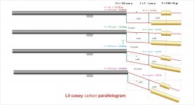
Hi Niffy, Walter, and someone else. Here a quick calculation (in grams, not mN!) of the behavior of the CW on my Lil Casey carbon parallelogram - real measures and weights.
Seems that there is in no VTF variation, even for large angles. Different from what I thought (very small at first, but increasing variations); maybe we can sleep peacefully, at least for this.
But, where i'm wrong?
carlo
Seems that there is in no VTF variation, even for large angles. Different from what I thought (very small at first, but increasing variations); maybe we can sleep peacefully, at least for this.
But, where i'm wrong?
carlo
Attachments
VTF
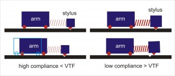
Hi, Carlo, Niffy. Excellent research. For now I would stick to my hypothesis 2022, because skiping occured on low compliance cartridge with 3- 3,5 gramm VTF required. Skiping near the inner groove was a reason for checking VTF on different diameters (because warps are larger on outer grooves, there no skiping occured). With high compliance carts no problems were encountered, even with 1gramm of VTF. Kind of paradoxal situation.
Walter
Last edited:
With high compliance carts no problems were encountered, even with 1gramm of VTF. Kind of paradoxal situation.
Yes, seems counterintuitive: greater VTF = greater trend to remain into the groove.
Me too had noticed that increasing the VTF over the recommended weight increased the skipping (it happened on the LC mk1, on steep warps). This was my reasoning: in presence of small defects the stylus tends to manage them with its compliance, before the arm with its inertia can follow him. Let's not forget that just a few microns are enough to get out of a groove. So a low compliance, that reacts more rigidly, tends to skip easier, if the arm doesn't follow immediately.
LC carbon has the effective masses reduced to 17 and 20, in any case not very low, and frictions are certainly not like those of a unipivot. Sufficient, but improvable.
So we have to continue working on frictions, weights and ... cables
carlo
Last edited:
Could these be used in a Lil Casey as bearings for the parallelogram?
And where do I get the or how do I make the needles?
VS-25 | Jewel Bearings, Vee Jewel Bearing Assemblies | Swiss Jewel
And where do I get the or how do I make the needles?
VS-25 | Jewel Bearings, Vee Jewel Bearing Assemblies | Swiss Jewel
No Koldby, probably not unfortunately - the knife blades are really smart bearings, simple, with very low friction and no chattering, but you can't use them here.
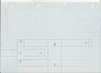
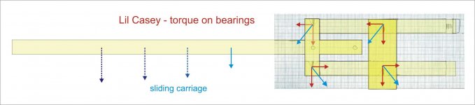
This because the weight of the rail itself, and the increasing carriage distance from the fulcrum generate a variable torque (opposite on upper and lower part of the parallelogram), and therefore loads out of vertical axis. Not the best condition for knife blade bearings.
There must also be no side play at all.
Jewell bearing, with their manufacturer's spindles (difficult to be diyed with proper tolerances and finish) should be the best solution, if one could get them.
From my experience with the pentips I suggest you to use really sturdy ones because the rail lever can generate (inadvertently, during positioning) significant loads.
carlo
... not be tubes....are you designing a different rail section? interesting - keep us informed
Last edited:
Jewels
Wide assortment, very impressive. Difficult to choose because of absence of metric measurements. Do they have European subdivision?Could these be used in a Lil Casey as bearings for the parallelogram?
And where do I get the or how do I make the needles?
VS-25 | Jewel Bearings, Vee Jewel Bearing Assemblies | Swiss Jewel
I do not know, but the transport expenses cannot be very high, as the bearings are very lightweight.Wide assortment, very impressive. Difficult to choose because of absence of metric measurements. Do they have European subdivision?
Could you please guide me to what pentips you are referring to. I could not find it in this thread.No Koldby, probably not unfortunately - the knife blades are really smart bearings, simple, with very low friction and no chattering, but you can't use them here.
This because the weight of the rail itself, and the increasing carriage distance from the fulcrum generate a variable torque (opposite on upper and lower part of the parallelogram), and therefore loads out of vertical axis. Not the best condition for knife blade bearings.
There must also be no side play at all.
Jewell bearing, with their manufacturer's spindles (difficult to be diyed with proper tolerances and finish) should be the best solution, if one could get them.
From my experience with the pentips I suggest you to use really sturdy ones because the rail lever can generate (inadvertently, during positioning) significant loads.
carlo
... not be tubes....are you designing a different rail section? interesting - keep us informed
No Koldby, probably not unfortunately - the knife blades are really smart bearings, simple, with very low friction and no chattering, but you can't use them here.
This because the weight of the rail itself, and the increasing carriage distance from the fulcrum generate a variable torque (opposite on upper and lower part of the parallelogram), and therefore loads out of vertical axis. Not the best condition for knife blade bearings.
There must also be no side play at all.
Jewell bearing, with their manufacturer's spindles (difficult to be diyed with proper tolerances and finish) should be the best solution, if one could get them.
From my experience with the pentips I suggest you to use really sturdy ones because the rail lever can generate (inadvertently, during positioning) significant loads.
carlo
... not be tubes....are you designing a different rail section? interesting - keep us informed
Just a crazy idea maybe:
What if the groove the knife (the knife itself of course steel) was seated in was made of a magnetic material, could this rectify the situation?
Wide assortment, very impressive. Difficult to choose because of absence of metric measurements. Do they have European subdivision?
I got my pivots from here
True Point (UK) Ltd - Precision engineers
Niffy
Hi Koldby
pentips: look carefully to Lil Casey carbon drawings and 3d visuals - on a post i've talked about the "tricks" of their implementation.
magnets - my memories of physics are foggy, but the situation should be like this (attachment). Magnets attraction on blades could maybe complicate it unpredictably.
What's important is that the parallelogram must be rigid (no flexure or play in any direction), light (extremely light), and without chattering (difficult with all those bearings). But above all with negligible frictions (difficult with all those bearings, again).
This is our diyer's fun
carlo
jewells - imho here are needed those with springs, and quite sturdy (not for watchmaker use) = rather bulky and heavy
Attachments
Thanks again carlo, now I get it I think.Hi Koldby
pentips: look carefully to Lil Casey carbon drawings and 3d visuals - on a post i've talked about the "tricks" of their implementation.
magnets - my memories of physics are foggy, but the situation should be like this (attachment). Magnets attraction on blades could maybe complicate it unpredictably.
What's important is that the parallelogram must be rigid (no flexure or play in any direction), light (extremely light), and without chattering (difficult with all those bearings). But above all with negligible frictions (difficult with all those bearings, again).
This is our diyer's fun
carlo
jewells - imho here are needed those with springs, and quite sturdy (not for watchmaker use) = rather bulky and heavy
Something like this idea?:
YouTube
Any particular maker that makes the best pen-tip's?
Yes - 2 mm diameter -. Often used for unipivots. -
Here 10 refills are available from any chinese store for 1 - 1,50 euro - less on black friday. You may choose instead those sold from famous luxury pen makers, manufactured in China for 1,50 $ the thousand.
The rest of the bearing is made with a threaded 3mm rivet and a 2,5 mm brass screw. On this you have to get a conical seat using a center drill, that gives a 120° angle. Better if polished with a small dremel tool.
An advice: Lil Casey is mechanically simple, but needs tight tolerances for the parallelogram and the carriage + rail system. Build it as an experiment to be further investigated, as a challenge, more than your next everyday TA.
carlo
your knife blade idea is clever: Don't give up, maybe working on it....
an eccentric idea*
background - yesterday putting a spray can of mosquito repellent on a table I saw it swinging several times before stopping: it surprised me, but that's the reason, probably. No magic, simply jel (attachment)
back to us - one of the bigger problems of linear TA comes from the eccentricities, that impose accelerations on the carriage often incompatible with its inertia / friction. The eccentricities are present on almost all of our beloved discs, and very difficult to overcome with practical systems.
However, unlike warps, they have two advantages: 1 - the amplitude is constant at any point on the disc - 2- the frequency is constant (one + - eccentricity every 1'/ 33.33). Every turn of the disc our carriage should move back and forth the same measure of the eccentricity, accelerating and slowing down with respect to the speed of movement due to the tracking.
This suggests that if we had a system that could "copy" this oscillating movement (small or large) and passively communicate it to the carriage, we could get an always constant side force.
This brings us back to my jel can: if the wheels of a Niffy's style carriage were hollow, and with a suitable viscosity jel inside .... without eccentricity the jel would spread evenly inside the wheel (with only a slight increase in friction) but at the first acceleration it would accumulate on one side and then synchronize with all subsequent movements. Easy to say, but not to do, you may easily imagine why.
Let's try another way. We have the usual Niffy's carriage, but connected to a weight W via a rigid rod. This creates a complex pendulum (to be set with a period = 1'/ 33.33) that oscillates on the CG. At the first eccentricity the carriage communicates the corresponding momentum to the pendulum. The pendulum inertia and sincronicity feeds back the movement to the carriage every turn...
carlo
* just for summer fun, while others are toying with bathing tonearms...
Attachments

- Home
- Source & Line
- Analogue Source
- DIY linear tonearm