AAAAAAAaaaaagggggggghhhhhhHHHHHHHHHHH.
Major disaster.
I've just discovered that I've suffered a massive computer catastrophe. Virtually all my turntable design files, calculations, drawings and experiments from 2013 onwards have mysteriously disappeared. Only files created or modified in the last year or so remain after then. To make matters worse my backup file has suffered the same loss. I've probably lost a hundred files including all the subchassis and plinth designs and calculations. Loosing all those experiment and test results is a major bummer. On the bright side, at least I finished building the deck long before I lost the files.
Sad sad Niffy.
Niffy,
That is a major loss for you and your DIY friends. You spent a tremendous amount of time and effort making a record of all your accomplishments. Any possibility of removing the hard drive and sending it to an expert ? Don't be surprised if you see a Chinese turntable / tonearm looking like yours on ebay !!!! Hope you will be able to retrieve the data somehow. Best of luck.
That is a major loss for you and your DIY friends. You spent a tremendous amount of time and effort making a record of all your accomplishments. Any possibility of removing the hard drive and sending it to an expert ? Don't be surprised if you see a Chinese turntable / tonearm looking like yours on ebay !!!! Hope you will be able to retrieve the data somehow. Best of luck.
I think I've worked out what happened by going back through the photo album on my phone and looking at the dates of each stage of construction. My old computer died in 2016. When I got a new computer I loaded all my files from my backup. Unfortunately I used an old backup device instead of the correct and up to date version. The missing files never made it onto my current computer. The correct backup storage device was used to store some music files for use at my wedding reception. In the tidy up after the reception this device was lost. I finished building the deck in late 2015. I did all the investigation and upgrading of the arm bearings in 2016 and I think I have these files as they were done on the new computer. I've lost everything from sometime in 2013 until 2016. This is the fine tuning and final designs of the subchassis, suspension and plinth. I was looking for calculations for belt length and tension and couldn't find the correct files which alerted me to the loss.
On a brighter note all my tonearm files seem to be intact.
Also I finished making the new idler wheels yesterday and they look like they have come out perfectly. I just have to fit them to the deck and run them in then I can start experimenting with belt tension and a nifty little idea I've had for running multiple belts that should hopefully improve the runout of the main bearing when playing unbalanced records. The new idlers are more accurately centered than the current ones and initially tests would indicate that they are lower friction and lower noise (not that the current ones were bad in any of these respects). The current idlers run in Teflon bushes, the new ones use the same pin bearings that I developed for the tonearm. Fingers crossed.
Niffy
Hi, Niffy,
That is good news that you figured out how the data was lost. Even though you have a back up for your data perhaps you should also put it on a memory stick. I was worried that some hacker stole your data. Hope you retrieve all your data.
Are the idler pin bearings the same size as your tonearm or are more beefy because of the added stresses involved ?
Hi all,
I was using double physical backups and probably got lazy with my backup routine. I'll check my wife's external hard drive as I might have stuck a copy on there at some point. I think the cloud might be a better solution for a double backup plan.
The bearings for the idlers are very similar to those for the arm. The original arm bearings were made erring on the side of caution, I could have used smaller radius but went for the sizes I did as they were the same as the jewelled bearings I was planning on eventually using. I have kept the radius of the pin the same but have decreased the radius of the vee slightly, this will increase the maximum load of the bearing. One of the problems with my current idler bearings is that the belt tension has to be kept low as the Teflon bushes are not robust enough. Hopefully the new bearings will allow higher tension. I'll run the new bearings at my current belt tension for a couple of weeks to check for wear then start experimenting.
Niffy
Although the new idler bearings are basically the same as the arm bearings the requirements for the two roles are quite different. The arm bearings need to have very low friction and operate in a stop/start manner. Their angular velocity will be very low, about 0.5rad/s maximum on a badly eccentric record. In contrast the idler bearings will be operated at a constant (hopefully constant) angular velocity of 27.7rad/s. Still relatively low but much higher than the arm bearings. Although keeping friction low is advantageous it doesn't have to be at the very low level that the arm requires. Both applications do require that the bearings be very quiet though the types of noise that is most important is different for each. With the idler bearings the main type of noise will be "rumble" though for bearings of this size the frequency will be quite high so it's more of a "rush". For the Tonearm the most problematic type of noise is chatter, the pin type bearing is excellent in not suffering this type of noise. Mechanical grounding is very important for the tonearm but much less so for the idlers. Both bearings will be operated at low loads, the idler bearings will have around 3-4times the load of the arm. The aim is to make the bearings just large enough to have long-term reliability but no bigger. Making them larger will increase both friction and noise. The idler bearings will probably be run with petroleum jelly lubrication in order to minimise noise. The arm bearings are run dry in order to minimise friction. I think that the pin bearings will work as well in the idlers as they do in the arm. I'm hoping to be able to fit the new idlers tomorrow, fingers crossed.
Niffy
Niffy
Niffy, I do have a question, as to bearing noises. For motor, platter bearing, as well as idler drive, I can clearly hear the noise, both directly with stethoscope and through the speakers. As to tonearm bearing, I'm unable to hear any kind of chatter, as well, as other noises (other than those, coming from the motor and drive)... What is your opinion of how chatter influence on sound happens, and how to detect it?
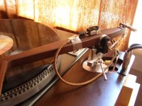
Picture shoves, how I tried to detect the arm bearing noise. Cartridge, placed directly on the arm with stylus in contact with the arm body near the horizontal bearings. Cables go into the phonostage.
Sorry, the arm is not linear.
Walter
Picture shoves, how I tried to detect the arm bearing noise. Cartridge, placed directly on the arm with stylus in contact with the arm body near the horizontal bearings. Cables go into the phonostage.
Sorry, the arm is not linear.
Walter
Attachments
Hi Joe,
Thanks for the fabulous offer. As I don't have any specific need for vespel at the moment I won't take you up on it, but thank you anyway. If my current idler experiment fails I might look at making some bushes from a higher tech material than Teflon. 1" diameter would be a bit extreme. The bushes in the current bearings are made from 1/16" Teflon rod.
Niffy
Niffy, I do have a question, as to bearing noises. For motor, platter bearing, as well as idler drive, I can clearly hear the noise, both directly with stethoscope and through the speakers. As to tonearm bearing, I'm unable to hear any kind of chatter, as well, as other noises (other than those, coming from the motor and drive)... What is your opinion of how chatter influence on sound happens, and how to detect it?
Picture shoves, how I tried to detect the arm bearing noise. Cartridge, placed directly on the arm with stylus in contact with the arm body near the horizontal bearings. Cables go into the phonostage.
Sorry, the arm is not linear.
Walter
Hi Walter,
Good question. Rumble and motor noise are generated independently from the record and arm and are relatively easy to measure in isolation.
The main source of energy that drives bearing chatter is the modulation of the groove itself. When playing a record the cartridge body/arm do not remain absolutely stationery but move out of phase with the groove modulation. The amount the cartridge moves is very small at high frequencies but can be surprisingly large at low frequencies. At 20hz the cartridge can be moving over 30% of the amount the stylus is moving. A 60um peek to peek modulation can cause the cartridge to be moving by more than 20um. At 50hz the cartridge moves about 4% as much as the stylus. By the time you get to 100hz it's only 1%. Even if your system can't play 20hz the arm can still be moving a large amount at this frequency.
Chatter is caused by this shaking of the arm making loose components in the bearing rattle.
Not all types of bearing suffer chatter, only those that have loose components. Ball race bearings are particularly prone to chatter as only the balls that are under load are restrained. It is possible to restrain all the balls in a ball race by applying a load parallel to the axis, pre-loading. This will increase the friction of the bearing. Applying grease or oil will damp the motion of the loose ball and will reduce or even eliminate chatter. Unfortunately this also increases friction. When using ball race bearings in a linear arm the bearings cannot be pre-loaded and have to be run dry. You can get away with pre-loading and lubricating the bearings in a pivoted arm as the bearing only rotates through a small angle and the armtube acts as a lever reducing the effect of bearing friction. The smaller angle of rotation can also reduce chatter as the movement at the bearing is lower. Compression waves travelling through the arm can also excite loose balls and may even be the predominant mechanism. There will be certain frequencies that cause chatter more than others, like the annoying rattle in your car that only occurs at certain speeds.
As chatter is at a much lower level than the groove modulation it is very difficult to isolate it. It is also difficult to alter the chatter to the bearing without also altering its level of friction or grounding. It is therefore difficult to determine whether a change in sound is due to reduced chatter or reduced friction or improved grounding. When developing my bearings I made 6 different rails and more than a dozen different wheels and bearings, including ball race. I tried to change as little as possible between each iteration so I could pin down what caused what change. I even made a rail that was designed to fail just so I could see if it failed in the way I expected. From this I determined that chatter plays a significant role in the sound quality of a mechanical linear tracking tonearm that utilises ball race bearings.
In extreme cases bearing chatter will add a harsh gratings edge to the sound. More commonly the effect is a more subtle veiling of detail and microdynamics.
I don't think your test set up is likely to reveal much. A phono cartridge works due to the relative motion between the stylus and cartridge body. In your set up both the stylus and cartridge are held stationery relative to the armtube. If it did reveal anything it would be how much the cartridge/arm is moving relative to the groove. If you could place the stylus directly against the bearing you might pick up something.
As long as it's DIY it doesn't matter if it's linear.
Niffy
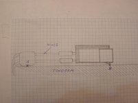
Niffy, thank you for detailed reply. As to my experiment with the cartridge, as tonearm parasitic sound sensor, it is rather encouraging. My first attempt was with a small microphone, and it happened not having enough sensitivity to detect any arm vibrations at all. Phono cartridge is a much better sensor, if placed properly. In my case, it has only two points of support: A made of four flexible wires, and B the stylus, cartridge acts as kind of effective mass, together with wires it makes tonearm-like arrangement, so the stylus able to detect tonearm body vibrations, further amplified by phonostage. Actually, I tried to hear, how the arm body resonates and sounds to make up my own opinion. In my case, wooden arm body has it's own sound, but it is of so miniscule level, that should be completely disregarded.
Attachments
Don't you just love it when an experiment fails
Hi all,
Still slightly off topic. I've fitted the new idler wheels and bearings. I wanted to make 4 changes over the previous setup even though they were almost perfect. The old ones had a very slight wobble (I'm only talking 10s of microns). Using techniques developed building the arm bearings they are now pretty much perfect . I wanted the ability to run higher belt tension so I could experiment to find the best possible. The new bearings are definitely able to take several times as much tension as the old. I also want to be able to use different or even multiple belts run in a rather unconventional manner. The new setup will allow this and will hopefully help to reduce platter runout. The old bearings were very quite. I could just hear them with a stethoscope pressed against the upper bearing mount, I could hear nothing from the lower mount. Unfortunately the new bearings are quite a bit noisier. If I strain my ears I can just hear the lower bearing. The upper bearing is quite noticeable. Now I have the joy of investigating tribology further and building more bearings until I get a perfectly quiet design. The increased bearing noise has only mildly effected sound quality, a slight veiling of micro dynamics, similar in nature to low level bearing chatter. It's one of those differences that's so slight it's difficult to pin down. I was surprised by how little difference the bearing noise made, the work put into resonance control in the subchassis seems to have paid off. After I've sorted the bearings I have the fun of investigating belts.
So I wouldn't call it a complete failure as 3 of the 4 improvements paid off. I think I'm on the right track.
Niffy
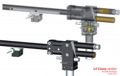
radial rail tonearm - carbon
I am slowly redesigning, simplifying the first Lil Casey, looking for a compact and easier to build solution. I have kept what showed to work well (non recirculating balls carriage - rotatable leveling base - lifter - CW regulation) trying to improve the rest (weight of vertical masses - vertical articulation - bearings). That's why a Ø12 mm carbonfibre tube, that should reduce the vertical mass to 25 gr ca: an acceptable value, similar to the horizontal one (< 20gr).
In addition to weight, the major revision relates to the parallelogram: the slanted version, that gave no real advantage, is substituted by a straight one with the rail between the levers to get the same couple on upper - lower bearings.
Bearings become pen-tips type, hoping to reduce the friction significantly. Unfortunately still couldn't get 4 pairs of jewel bearings without opening first a watch factory.
As usual my design refers to my tools, my skills, and materials I can find. I'm not saying it's a tonearm for newbies but needs only patience, accuracy. and simple tools (no lathe)
Sorry, no fancy tech.
carlo
Any advice?
Attachments
Hi Carlo,
You sometimes find used jeweled bearing parts on ebay.
100x holed watch jewels new old stock repair ruby hole watchmakers jewel parts | eBay
100x Top cap jewels for watch new old stock repair watchmakers parts watches | eBay
These are the ring and end cap type bearing in assorted sizes. Might be a help.
Niffy
Thanks for links, Niffy. Finally something useful, even if I'd like to find the springed version V bearings with their pivots. Banggood, Aliexpress and some sites of Swiss and American producers seem all B2B oriented.
Now a friend told me about a repairer of industrial clocks here in the area, so I'll try first to hear him.
Hoping to avoid tilts, I've made some tests of carriages on a square section, but without satisfactory results without greatly increasing the base, and therefore the overall weight. Add to this that square tubes in carbon > 8x8 are almost unavaible, and I'm back to the round solution, already tested.
Hope the carbon tube could be sufficiently straight, hard and smooth for the task. Unlike you I have no experience with carbon (just used for the arm wand)
carlo
I read about your computer. Horrible. Have you heard those who recover data from broken hard drives? sometimes miracles do happen
- Home
- Source & Line
- Analogue Source
- DIY linear tonearm