Hi carlthess40,I no longer can build things like that any longer. I have severe carpal tunnel syndrome in both hands and arthritis and I’ve already had two back surgeries and need one more
I am a highly accomplished machinist with the wood and metal and also a very accomplished welder. I’ve been a master mechanic for 45 years and with all of the years of doing this type of work has taken a toll on my body
I was hoping to find someone who has one or who can make one to a certain level that I could finish or take over a project
I do agree with you 100% that you do need to have the length of the arm as short as possible, the longer the arm, the less stiffness you have and the arm and start to transfer some vibrations through the arm itself from the needle. It’s basic engineering and physics
I just wish my hands would work a 1/10 of a%
As what my Head has gone through it with ideas for making turntables and arms
I have a bunch of 1 1/2 bulletproof glass that I am wanting to make a turntable out of It
I just need to get out to my brothers and use his shop and start milling and running the lathe to make some parts
You have many sympathizers here and elsewhere about the impact of carpal tunnel syndrome and arthritis on your abilities, and your hobby.
[My apologies to all about this post not belonging, so I will say only one thing more.]
If one has to get back to the job quickly, surgery is probably best, but if you have time (e.g. retired), go for the steroid injection(s). It takes longer, but if you do respond, the end result will likely be better.
Andy
I’ve tried so many different things
Shots in the back and neck. And everything in between lol
I only went with the surgery after 8 years of trying every other option and I was losing the Ability to use my legs. It sucks to stand and fall over. Lol. I did get back about 70% of my leg feelings
Shots in the back and neck. And everything in between lol
I only went with the surgery after 8 years of trying every other option and I was losing the Ability to use my legs. It sucks to stand and fall over. Lol. I did get back about 70% of my leg feelings
Last edited:
Frank is certainly a very clever man. He was using the inner race as a wheel which had a groove which sat on his rail. Offsetting the bearing from the wheel part to preload the bearing is a good idea. I was inspired by this idea when making the wheels for my arm. I couldn't find bearings of suitable size to repurpose for my design. I did however find some very small tungsten carbide wedding rings that were the perfect size. Tungsten carbide is an even better material than that of the inner race for the purpose of making wheels.
mea culpa
....The coefficients found for non recirculating are about 0.002, that with my cart of 14.5 grams give 0.290 mN. I have found half of it, which is incredibly low.... (nocdplz)
That simple bearing couldn't be better of a sophisticated one like yours, Niffy, even with less weight. That's why the calculation with your method: that gave me, of course, an absurd result.
So I reviewed my pendulum measurements and maybe found the mistake: to calculate potential energy was used - 0.0045 Kg * h - instead of Newtons - 0.044 N - one zero less
So the results are now much more realistic.
Lil Casey (radial rail) F = 1.41 mN.
JR Casey (normal rail) F = 3.75 mN,
Rabbit (belted PLT) F = 2.54 mN
Unipivot F = 0.52 mN
But i'm not still convinced:
1.41 * 20 = 28.2 um = 0.028 mm (friction * compliance = bending); arcsin (28.2 / 6000) = 0.27 ° (arcsin (bending / length)). Near yours, but seems again too low. On the frames was 0.13 mm (+ - 0.65mm). Same calcs repeated with 10mN (1g !) gave 0.2 mm bending, 1.9 ° angle. Too low again, imho. This measures do not bring skipping, while 1 gram is more than enough
Tests to do: measure the bending with 0.5 - 1.0 g of SF (on a close up photo) -- Repeat the shooting of the eccentricity closer and sharper (damn pocket digicameras) and carefully re-measure the frames.
carlo
Last edited:
mea culpa
....The coefficients found for non recirculating are about 0.002, that with my cart of 14.5 grams give 0.290 mN. I have found half of it, which is incredibly low.... (nocdplz)
That simple bearing couldn't be better of a sophisticated one like yours, Niffy, even with less weight. That's why the calculation with your method: that gave me, of course, an absurd result.
So I reviewed my pendulum measurements and maybe found the mistake: to calculate potential energy was used - 0.0045 Kg * h - instead of Newtons - 0.044 N - one zero less
So the results are now much more realistic.
Lil Casey (radial rail) F = 1.41 mN.
JR Casey (normal rail) F = 3.75 mN,
Rabbit (belted PLT) F = 2.54 mN
Unipivot F = 0.52 mN
But i'm not still convinced:
1.41 * 20 = 28.2 um = 0.028 mm (friction * compliance = bending); arcsin (28.2 / 6000) = 0.27 ° (arcsin (bending / length)). Near yours, but seems again too low. On the frames was 0.13 mm (+ - 0.65mm). Same calcs repeated with 10mN (1g !) gave 0.2 mm bending, 1.9 ° angle. Too low again, imho. This measures do not bring skipping, while 1 gram is more than enough
Tests to do: measure the bending with 0.5 - 1.0 g of SF (on a close up photo) -- Repeat the shooting of the eccentricity closer and sharper (damn pocket digicameras) and carefully re-measure the frames.
carlo
Hi Carlo,
I just want to make sure that I am reading your post correctly. Your recalculated frictions look reasonable.
Are you saying that you filmed the arms on a record that had an eccentricity of 0.65mm (resulting in a 1.3mm side to side movement) and that the observed stylus deflection was greater than calculated?
Inertia is unlikely to cause much deflection. A 14.5g carriage on this record with a 20um/mN cartridge should show a deflection of only about 2.3um (0.022° with your cartridge) which would be very difficult to detect.
I mentioned earlier that most cartridges have falling compliance with increasing frequency. Compliance is at a maximum when stationery (static compliance). It is possible that your cartridge has a greater than normal difference between dynamic and static compliances. What cartridge are you testing with? I do recall hearing that, I think it was, the shure V15 cartridges almost doubled in this respect, but this would be an extreme example. If your cartridge is like this then observed deflections could be almost double those calculated. I cannot remember the source of this information or if I am remembering it correctly so this should be taken with a pinch of salt. My observations would suggest that the dynamic and static compliances do not vary from each other significantly with my ortofon cartridge.
I'm sure you will already have accounted for cable dressing but I'll check anyway. Were the arms wired the same when using the pendulum rig and when filming?
Hopefully you can find the discrepancy, if there is one, and we can learn a bit more about cartridges in the process.
Niffy
Hi carlthess40,
Sorry to hear about your health problems. I hope you get back to making swarf soon.
1 1/2inch bullet proof glass should be great for turntable construction. Do you know what the different layers are made of and how many layers there are? I imagine that water jet cutting would be ideal for cutting it to shape. You could create something spectacular looking. Good luck.
Niffy
First of all Niffy, thank you for the time wasted for me, hope it will also serve others, as few people measure, stopping too early to enjoy the results. I like the measures, but my math is reduced to that of the crows, who can only count up to 7. I get mixed up with comma zero zero, damn MKS.
I answer in a row
1 - yes, 141 milligrams seems ok, the carriage runs very well but 14 mgr was really impossible. (owning a pharmacy mechanical scale I know what they are)
2 - sorry, typing error- on my test disk I have an eccentricity of 1, 3 mm that on the video gave 1.18 mm of carriage movement + 0.13 mm of stylus bending (that is + - 0.065 back and forth, not 0.65 as I wrote).
The calculations made make me think that the compliance given by builders is relative only to the micro-movements on the groove (for the resonance matching): more the side force used on calcs more the result become doubtful: 1.9 ° with 1 gr is completely unlikely.
The problem is that on such things the variables are so many (so it is easy to go off road: I have seen calculating the skipping force with the inclined plane, or affirm that the SD is equal to the VTF) and the measures so delicate to require a well equipped laboratory and skilled technicians.
So few measures around, maybe claims sell better and cost less.
ciao - carlo
no cable used for carriage of linears (alters too much the measures, and inconsistently)
rabbit and unipivot with soft plastic insulated ones (for the unipivot maybe all the force neasured is that for twisting)
Last edited:
Hi all,
Apologies (again) for my Noob-ness
Trying to understand-according to Kuzma:
“The effective mass of a tonearm is a figure in grams. It represents the ‘force’ needed on the diamond tip to move the tube at the bearings.”
but how does this translate to deflection of the cantilever-in mm I mean
I can’t connect this to the calculations above- what am I missing here?
Thx
Coolerooney
Hi all,
Apologies (again) for my Noob-ness
Trying to understand-according to Kuzma:
“The effective mass of a tonearm is a figure in grams. It represents the ‘force’ needed on the diamond tip to move the tube at the bearings.”
but how does this translate to deflection of the cantilever-in mm I mean
I can’t connect this to the calculations above- what am I missing here?
Thx
Coolerooney
Hi coolerooney.
It's very difficult to discribe effective mass in a couple of short sentences. Frank Kuzma is a very talented guy so I'm a bit surprised to see this quote being attributed to him. It seems to describe bearing friction more than it does effective mass.
Effective mass is used to describe a property of tonearms that pivot about a point. Conventional arms pivot both horizontally and vertically. Linear tracking arms only pivot vertically, the entire arm moves horizontally.
If the stylus moves by a certain distance the parts of the arm that are closer to the pivot will move a smaller distance. A point half way between the stylus and pivot will move half as much as the stylus. More importantly for there to be movement there will also be an acceleration. The acceleration at the half way point will also be half that at the stylus. So the stylus will not feel the full mass of that point. It will feel only a quarter of its full mass. For points even closer to the pivot the stylus will feel even less. Do this for every point on the arm and add them together and you get the effective mass. You can think of the effective mass as a single point mass located at the stylus that has the same effect as the entire arm.
Translating the effects of effective mass into stylus deflection is somewhat more complicated. The effective mass in combination with the compliance (springyness) of the cartridge creates a spring-mass-damper system.
The relative motion of the stylus to cartridge body will be both frequency and amplitude dependant. This system will have a certain frequency at which it resonates. You want to keep this frequency above the frequency at which warps or eccentricity occur and below the lowest frequency of the music. Increasing effective mass will reduce this frequency and decreasing mass will increase this frequency. Every cartridge will have an ideal effective mass of arm to work at its best.
There is a lot more to effective mass than I've outlined here. I wrote a couple of quite extensive articles in this thread concerning effective mass a couple of years ago that showed how to calculate it and how it effects sound quality.
I hope this helps.
Niffy
Hi Niffy,
Thx
The Kuzma paper
http://www.kuzma.si/media/uploads/files/KAA 2016 LECTURE 2017.pdf
Page 16, 17,18
Your posts on eff mass
effective mass
https://www.diyaudio.com/forums/analogue-source/238027-diy-linear-tonearm-207.html#post4755990
Coolerooney
Thx
The Kuzma paper
http://www.kuzma.si/media/uploads/files/KAA 2016 LECTURE 2017.pdf
Page 16, 17,18
Your posts on eff mass
effective mass
https://www.diyaudio.com/forums/analogue-source/238027-diy-linear-tonearm-207.html#post4755990
Coolerooney
Last edited:
I'll give the kuzma link a good perus when I get a chance, looks like he's covering all the main points in a bit of detail. Should be a good read. Thanks for the link.
That's the first part I wrote. I reposted it in this thread and added a second part. I'll have to see if I can find it.
Niffy
That's the first part I wrote. I reposted it in this thread and added a second part. I'll have to see if I can find it.
Niffy
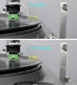
Bending test with 1 gr SF traction
More difficult than expected, Niffy, because these small digicameras decide by themselves where to focus (the base of the arm, damn idiot) and cheating them is not easy.
As predicted, with the right VTF the traction of 1 gram brings skipping, and therefore nothing could be measured: only with 4.5 gr. VTF it was possible, but bending was visibly reduced due the elastomer too crushed upwards. It should also be noted that the traction is a bit less than 1gr, for the pulley friction.
Practically identical results for two original AT95 styli, one new the other quite used
The results are in the picture: bending 0.37 mm ca = 3.5 ° degrees. Calculations with static compliance would give instead 10mN * 20 = 0.2mm = 1.9° degrees - with the dynamic compliance 10mN * 6.5 = 0.065mm = 0.62° degrees.
This seem to confirm the measurements on the video for Lil Casey, different in the same way from calculations: 1,41mN * 20 = 0,028 mm bending calculated, half of 0.065 observed on video
carlo
Attachments
Hi Coolerooney,
Just read the full Kuzma article. The quote makes a lot more sense in context. I'm a big kuzma fan, the 4 point is one of the finest arms ever made and the airline is no slouch either.
Niffy
Hi Niffy,
Yes, I thought too it was a good paper, but still trying to get these things together- if the Kuzma statement is correct on eff mass, then how does this translate from say, 20 gr eff TA mass into cantilever displacememt relative to the cartridge body? How does the compliance factor into this?
Thx
Coolerooney

Hi Carlo,
Neat experiment. It must have been a pig to get lined up and in focus. I'm not sure you've taken the measurements correctly, it was a small deflection relative to the size of the photo and didn't look as much as 0.37mm to me. I downloaded the photos and blew them up so that the front face of the stylus body was 100mm across. I set a 100mm wide box aligned with the stylus body. I set a second box aligned with the right hand side of the first box and with its left hand side aligned with the center of the stylus. The second box in the photo with no traction was 50.4mm wide. With the 10mN of traction it was 52.4mm wide. A difference of 2mm. I think these measurements are accurate to +/-0.2mm. If I assume that the front face of the stylus body is 10mm wide this would indicate that the stylus was deflected by only 0.2mm and not the 0.37mm you measured. Could you please measure the actual width of the stylus body for me as I couldn't find it in any specs. I had to estimate the 10mm from measuring a photograph of the underside of an at95e and comparing the distance between the bolt holes to the stylus body's width. A 0.2mm deflection would be consistent with a compliance of 20um/mN which would mean that the dynamic and static compliances are the same. If anyone else would like to check it would be useful to have a third pair of eyes on this. If the deflection really is only 0.2mm then it would suggest that my calculations for tracking errors are reasonably accurate. I took great care when measuring as I want to be as honest with myself, and you, as possible and to avoid any confirmation bias. You don't learn anything going down that path.
I really am going to have to get one of these USB microscopes, they look like great fun.
Niffy
Hi Niffy,
Yes, I thought too it was a good paper, but still trying to get these things together- if the Kuzma statement is correct on eff mass, then how does this translate from say, 20 gr eff TA mass into cantilever displacememt relative to the cartridge body? How does the compliance factor into this?
Thx
Coolerooney
Hi Coolerooney,
I'll try to answer this using a slightly different example to the one you suggested.
If I have a 20um/mN cartridge in an arm with effective mass of 12.67g I will get a resonance of 10hz. If playing a record with a 0.5mm eccentricity (1mm visible wobble) the cantilever will be deflected, due to the inertia of the arm, by a maximum of 1.4um. With a 6mm cantilever (Carol's cart) this equates to a tracking error of 0.013°
If I quadruple the mass of the arm to 50.7g the resonance frequency will be 5hz. The maximum deflection will now be 6um which equates to a tracking error of 0.057°, still to little to be overly concerned with.
However the movement of the cartridge body above resonance, in the audio band, is reduced by 12dB with the heavier arm. This makes a significant difference especially at very low frequencies.
The equation I used to determine these figures is a bit of a mouthful and takes the damping of the cartridge and the resonant frequency of the system into account . For determining the deflection due to eccentricity a much simpler equation can be used.
d=emcw^2
Where d is stylus deflection (um)
e is eccentricity (mm) (half the amount the cartridge moves)
m is the effective mass (kg)
c is compliance (um/mN)
w is angular velocity (rad/s) (3.49 at 33.3rpm)
For the example of the 20um/mN cart on 12.67g arm deflection would be 1.54um. Reasonable similar to more accurate equation, the difference is due to the more simple equation not taking damping into account.
Niffy
- Home
- Source & Line
- Analogue Source
- DIY linear tonearm